What's the best way to achieve an unequal power split?
By Doug Jorgesen, Posted Thu Sep 26 2024 00:30:00 GMT+0000 (Coordinated Universal Time)
“I want to split a signal non equally.” This is a common problem for RF and Microwave engineers. What is the best way? Here is a rundown on all of the options, with recommendations depending on whether you are building your system using surface mount, chip and wire, connectorized module, or waveguide components. In the below we’ll assume that the phase relationship between the through path and the coupled path is not important. In general we’ll go from solutions that are suitable for highly uneven split values to equal power splits.
1) Pick off Tees

Suitable division values: Approximately 40 to 20 dB
Circuit Description: Pick-Off Tees use a single large value resistor placed on the line
Benefits: Pick off tees are super easy to implement and small and can have very low insertion loss if the pick off value is low
Drawbacks: Electrical performance is poor, and directivity is nonexistent. Additionally the return loss is terrible for pick off values above around -20 dB. Power handling is very poor, and high frequency matching and insertion loss are very poor due to the parasitics of the surface mount resistor. Only suitable for low frequency (< 6 GHz) and low value splits (-20 dB).
Implementation:
Printed Circuit Board: Simply put a resistor to the side, and keep the main trace and side trace at 50 ohms. The coupled port in particular will be highly mismatched.
Bare die: This is probably not a good option in bare die. You would need to design a thin film or custom die with a 50 ohm line and a printed resistor.
Connectorized Module: Marki offer Connectorized Pick-Off Tees to 30 GHz
Waveguide: These are not a good choice for waveguide systems, as directional couplers are easier to build and have better electrical performance.
2) Unequal Resistive Power Splitters
Suitable division values: Approximately 40 to 0 dB
Circuit Description: Similar to pickoff tees, a resistive power splitter adds series resistors to the through line to improve the matching. Perfect 50 ohm matching can be achieved at low frequencies before parasitic elements take over.
Benefits: Easy to implement and well matched at low frequencies, broadband
Drawbacks: Additional loss is incurred on the main line compared to a pickoff tee. Also has no directivity or isolation between output ports.
Implementation:
Printed Circuit Board: Can be easily printed on a board, resistor values are available here.
Bare die, Connectorized Module, Waveguide: Marki does not currently offer uneven resistive power dividers, but contact [email protected] if you have a requirement. Equal power resistive power dividers are available in connectorized and surface mount packages.
3) Directional Couplers
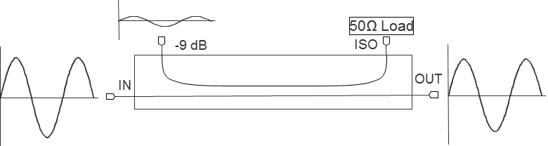
Suitable division values: Approximately 30 to 8 dB
Circuit Description: Directional Couplers consist of two carefully designed coupled transmission lines. The coupling can be forward or backward, but backward couplers are the gold standard as they can have excellent electrical performance over a wide bandwidth.
Benefits: Directional couplers are generally the best choice for uneven splitting applications. They offer low insertion loss with excellent return loss and directivity when properly designed. The power handling is very high, making them excellent for power monitoring and leveling.
Drawbacks: Design of directional couplers, and particularly broadband directional couplers, is challenging and subject to the fabrication tolerances of the circuit board. In a make/buy decision, it is almost always better to buy these components.
Implementation:
Printed Circuit Board: Designing a narrowband directional coupler is documented many places. It typically requires schematic level simulation software such as ADS from Keysight or Microwave Office from Cadence. Superior results are achieved with full 3D simulation software. Alternatively Marki offers surface mount directional couplers from 2-22 GHz.
Bare die: Marki does not currently offer directional couplers as bare die, but contact [email protected] if you have a requirement.
Connectorized Module: Marki offers a complete line of directional couplers from 500MHz to 110 GHz
Waveguide: Marki offers waveguide directional couplers with a variety of flanges from 26.5 to 110 GHz
4) Rat Race and Branchline Couplers

Suitable division values: Approximately 0 to 8 dB (depending on substrate dielectric and thickness)
Circuit Description: Rat Race and Branchline Couplers are both typically built as printed microstrip structures, and they are typically equal power division. However, they can be made uneven by modifying the impedances of the lines. The limit for power division is the achievable ratio of impedances on the circuit board. For example, a 10 dB ratio on a branchline coupler requires an impedance of 158 ohms. This requires a trace of 0.0002” if using a standard 0.008” substrate with a dielectric of 3.55. This is too small for manufacturability. However, if a specialty substrate with a dielectric of 2.2 and a thickness of 0.030” is used, the trace width is reduced to 0.0054” , which may be manufacturable. Good results should not be expected for split ratios this high, however, using specialty materials without full 3D simulations. Realistically values from even splits to around 5 dB are realistic.
Benefits: As mentioned here, these couplers are easy to implement, planar, and low loss, as well as offering isolation between outputs.
Drawbacks: Both couplers are narrowband and physically large, especially at lower frequencies. Acceptable for class projects and possibly some low cost, low volume applications.
Implementation:
Printed Circuit Board: Described above.
Bare Die, Connectorized Module, and Waveguide: Not available from Marki
5) Wilkinson Power Divider/Splitter/Combiners

Suitable division values: Approximately 0 to 4 dB (depending on substrate dielectric and thickness)
Circuit Description: Similar to the branchline and rat race couplers, the Wilkinson power divider is typically implemented as a printed microstrip circuit with resistors either printed or more typically soldered on.
Benefits: As detailed in our Power Dividers & Directional Couplers Primer, the Wilkinson power divider is the superior choice in nearly all cases for broadband, equal power division. It is widely used and implemented in many circuits due to its low loss, good match, and high isolation between output ports.
Drawbacks: Uneven power division ratios are highly limited in Wilkinson dividers again due the achievable impedance ratios. For example a 4 dB uneven Wilkinson design would require an impedance of 117 ohms, which is typically difficult to implement.
Implementation:
Printed Circuit Board: Narrowband Wilkinsons can easily be printed on a circuit board, but they are large and have poor performance compared to tiny surface mount options available on the Marki catalog from 400 MHz to 70 GHz.
Bare die: Marki offers bare die Wilkinson Power Dividers from 500 MHz to 26 GHz. Higher frequency and custom options are available by contacting [email protected].
Connectorized Module: Marki offers a complete line of 2, 3, and 4 way Wilkinson Power Splitters from 500MHz to 110 GHz
Waveguide: Marki offers waveguide power dividers with a variety of flanges from 50 to 110 GHz
Bonus - Quadrature Hybrid (3 dB) Couplers
Suitable division values: 0 dB
Circuit Description: Quadrature Hybrids are actually composed of two directional couplers with an 8 dB coupling value back to back, since this is typically the highest value that can be achieved with a directional coupler
Benefits: Quadrature Hybrids have many of the benefits of Wilkinson Power Splitters (broadband, high isolation), but very high power handling and DC isolation between the through path and the coupled path.
Drawbacks: Higher loss than Wilkinson Power splitters, and difficult to design on your own.
Implementation:
Printed Circuit Board: Don’t try to build your own here, Marki offers surface mount quadrature hybrids from 2-18 GHz.
Bare die: Marki offers bare die quadrature hybrids from 2-42 GHz.
Connectorized Module: Marki offers a complete line of quadrature hybrids from 500MHz to 110 GHz
Waveguide: Marki offers waveguide directional couplers with a variety of flanges from 26.5 to 110 GHz
Further Reading:
Power Dividers & Directional Couplers Primer: Overview and Definition of Terms
6 Ways to Make an N-Way Power Splitter
Yes, Wilkinson power dividers also work for combining data
How do signals cancel in a microwave power divider?
How do RF and Microwave Power Splitters, Dividers, and Combiners Work?
Related Application Notes
An Introduction to Noise, Linearity, and Dynamic Range in RF and Microwave Receivers
By Doug Jorgesen
|Published on: Wed Aug 28 2024 18:08:35 GMT+0000 (Coordinated Universal Time)
A Channelized 2-18 GHz Microwave Receiver Block Diagram
By Doug Jorgesen
|Published on: Wed Jul 09 2025 23:18:00 GMT+0000 (Coordinated Universal Time)
Rules of Thumb for Designing a Landing Pattern
By Jessica Kaur
|Published on: Thu May 07 2026 21:20:09 GMT+0000 (Coordinated Universal Time)