Absolute Maximum Ratings
| Parameter | Maximum Rating | Unit |
|---|---|---|
| RF Power Handling , Average | 4 | W |
| RF Power Handling , Peak | 20 | W |
Sales: 408-778-9952 | General: 408-778-4200 | Fax: 408-778-4300
Sales & Customer Support: [email protected]
Tech Support: [email protected]
The HLM-40 is a high-power GaAs Schottky diode signal limiter featuring high IP3 and high-power handling. It offers low insertion loss and low return loss from DC through Ka band and has a typical 1dB compression point of 15dBm. Its high-power handling makes it ideal for protecting sensitive components and for applications requiring high linearity.

N/A
N/A

HLM-40CH
High Power 40GHz Limiter
| Revision Code | Revision Date | Comment |
|---|---|---|
| A | 2025-03-19 | Updated Catalog Outline | ECN 24096 |
| B | 2026-06-02 | Added Recovery Time and Spike Leakage |
HLM-40CH
High Power 40GHz Limiter
| Parameter | Maximum Rating | Unit |
|---|---|---|
| RF Power Handling , Average | 4 | W |
| RF Power Handling , Peak | 20 | W |
| Parameter | Details | Rating |
|---|---|---|
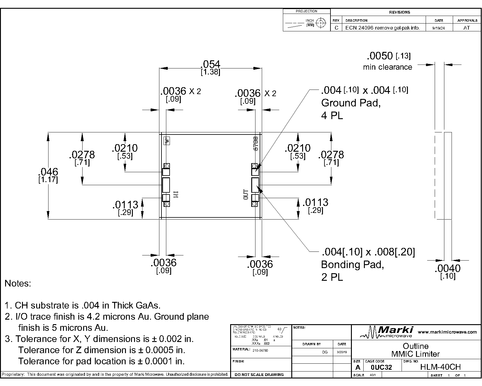
| Dimensions | - | 1.38 x 1.17 mm |
HLM-40CH
High Power 40GHz Limiter
| Parameter | Test Conditions | Minimum Frequency (GHz) | Maximum Frequency (GHz) | Min | Typ | Max | Unit |
|---|---|---|---|---|---|---|---|
| Insertion Loss | - | 0 | 40 | - | 0.5 | 1.5 | dB |
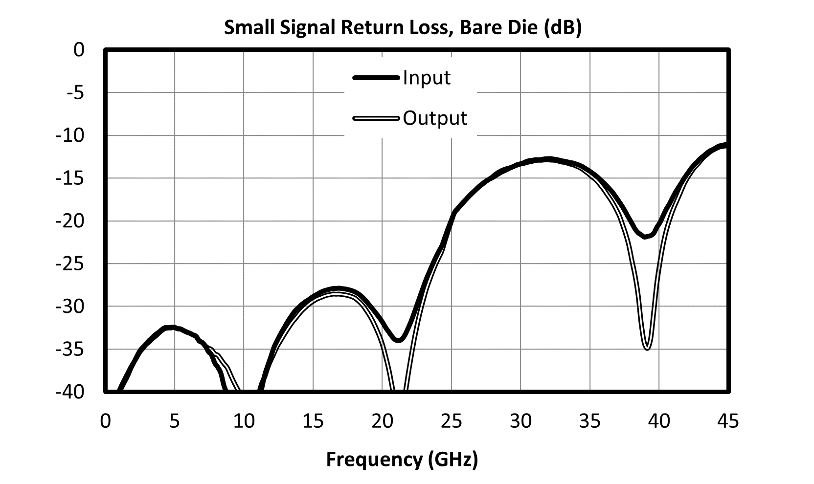
| Return Loss | - | 0 | 40 | - | 26 | - | dB |
| Flat Leakage | - | - | - | - | 18 | - | dBm |
| Flat Leakage | - | - | - | - | 18 | - | dBm |
| Input P1dB | - | - | - | - | 15 | - | dBm |
| Spike Leakage | - | - | - | - | 0.1 | - | erg |
| Recovery Time | - | - | - | - | 8 | - | ns |
| Parameter | Test Conditions | Minimum Frequency (GHz) | Maximum Frequency (GHz) | Min | Typ | Max | Unit |
|---|---|---|---|---|---|---|---|
| Insertion Loss | - | 0 | 40 | - | 0.5 | 1.5 | dB |
| Return Loss | - | 0 | 40 | - | 26 | - | dB |
| Flat Leakage | - | - | - | - | 18 | - | dBm |
| Flat Leakage | - | - | - | - | 18 | - | dBm |
| Input P1dB | - | - | - | - | 15 | - | dBm |
| Spike Leakage | - | - | - | - | 0.1 | - | erg |
| Recovery Time | - | - | - | - | 8 | - | ns |
HLM-40CH
High Power 40GHz Limiter

.svg)
.svg)
.svg)
.svg)


HLM-40CH
High Power 40GHz Limiter


.svg)
.svg)
.svg)
.svg)
.svg)
HLM-40CH
High Power 40GHz Limiter
.svg)
HLM-40CH
High Power 40GHz Limiter
Performance plots for the connectorized module are shown for measurements where directly probed measurements of the die are unavailable. Note that the following measurements include losses from connectors and microstrip traces.
.svg)
.png)
.svg)
.svg)
.svg)
.svg)


HLM-40CH
High Power 40GHz Limiter


.svg)
.svg)
.svg)
.svg)
.svg)
HLM-40CH
High Power 40GHz Limiter
.svg)
HLM-40CH
High Power 40GHz Limiter