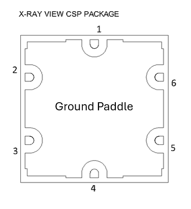
Port Diagram
Sales: 408-778-9952 | General: 408-778-4200 | Fax: 408-778-4300
Sales & Customer Support: [email protected]
Tech Support: [email protected]
The MQH-1329CSP3 is a MMIC 13 - 29 GHz quadrature hybrid. Passive GaAs MMIC technology allows production of smaller constructions that replace larger form factor circuit board constructions. The MQH-1329CSP3 exhibits excellent amplitude balance with broadband quadrature phasing between output ports. Low variation allows for accurate simulations using the provided S4P file taken from measured production units. Tight fabrication tolerances allow for less unit to unit variation than traditional splitter/combiner technologies.
N/A

| Part Number | Description | Package | Green Status | Product Lifecycle | Export Classification |
|---|---|---|---|---|---|
| MQH-1329CSP3 | MMIC 13 - 29 GHz 90° Hybrid Coupler | CSP3 | RoHS REACH | Released | EAR99 |
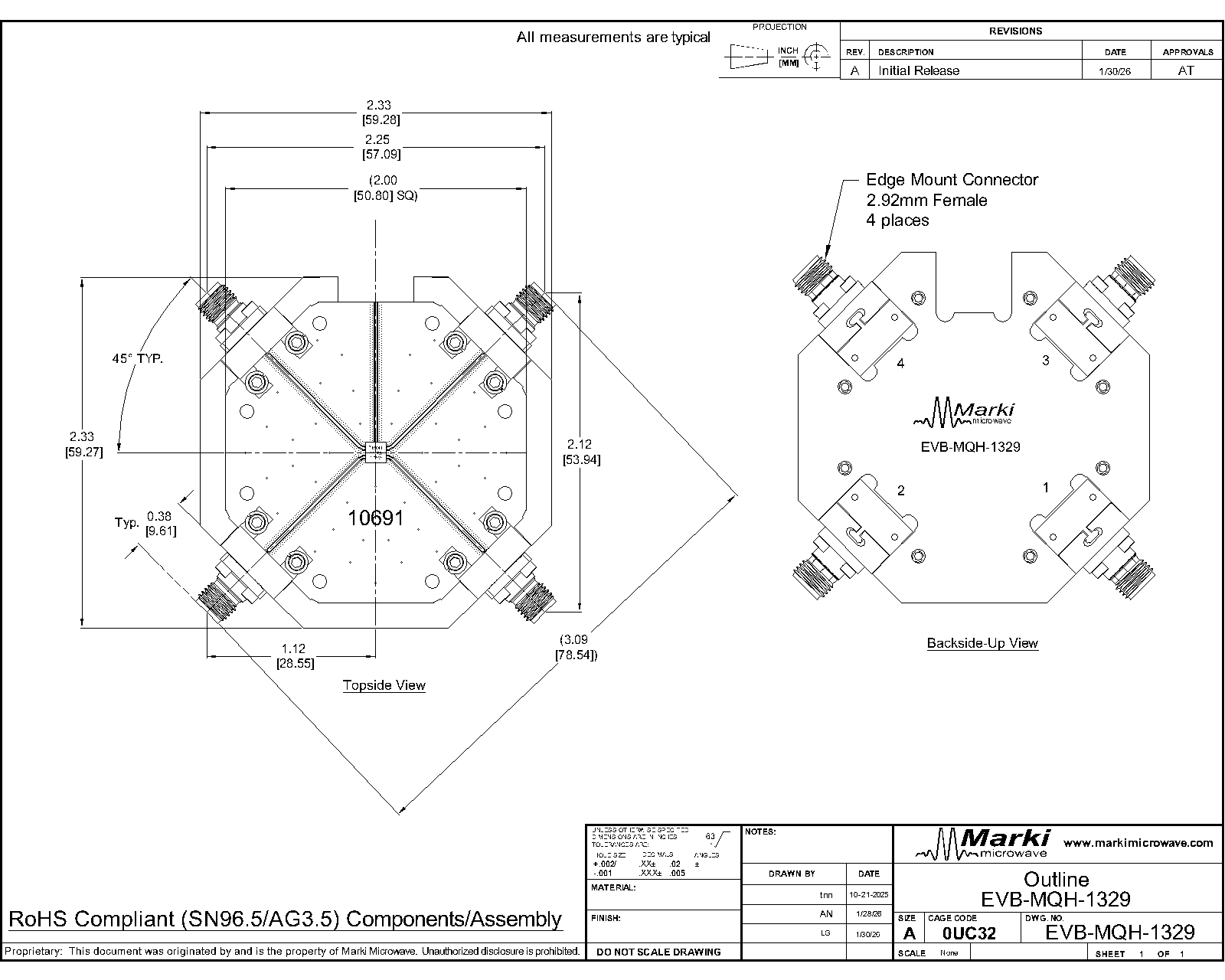
| EVB-MQH-1329 | Evaluation Board, 13 - 29 GHz MMIC 90° Hybrid Coupler | EVB | RoHS REACH | Released | EAR99 |
| Part Number | Description | Package | Green Status | Product Lifecycle | Export Classification |
|---|---|---|---|---|---|
| MQH-1329CSP3 | MMIC 13 - 29 GHz 90° Hybrid Coupler | CSP3 | RoHS REACH | Released | EAR99 |
| EVB-MQH-1329 | Evaluation Board, 13 - 29 GHz MMIC 90° Hybrid Coupler | EVB | RoHS REACH | Released | EAR99 |
MQH-1329CSP3
MMIC 13 - 29 GHz 90° Hybrid Coupler
| Revision Code | Revision Date | Comment |
|---|---|---|
| - | 2026-04-16 | Initial Release |
MQH-1329CSP3
MMIC 13 - 29 GHz 90° Hybrid Coupler
MQH-1329CSP3
MMIC 13 - 29 GHz 90° Hybrid Coupler
| Port | Function | Description | DC Equivalent Circuit |
|---|---|---|---|
| Ground Paddle | Gnd | Ground paddle should be connected to RF ground |  |
| Pin 1 | NC | Pin 1 is not internally connected. It can be connected to ground for normal operation. | - |
| Pin 2 | Isolated | Pin 2 is isolated from the input. It is DC open to the other pins and open to ground. It should be connected to a 50 Ω load for normal operation. |  |
| Pin 3 | RF Input | Pin 3 is used as input. It is DC open to the other pins and open to ground. | |
| Pin 4 | NC | Pin 4 is not internally connected. It can be connected to ground for normal operation. | - |
| Pin 5 | 90° Output | Pin 5 is 90° output. It is DC open to the other pins and open to ground. | |
| Pin 6 | 0° Output | Pin 6 is 0° output. It is DC open to the other 4 pins and open to ground. | |
MQH-1329CSP3
MMIC 13 - 29 GHz 90° Hybrid Coupler
| Port | Function | Description | DC Equivalent Circuit |
|---|---|---|---|
| Ground Paddle | Gnd | Ground paddle should be connected to RF ground | |
| Pin 1 | NC | Pin 1 is not internally connected. It can be connected to ground for normal operation. | - |
| Pin 2 | RF Input | Pin 2 is used as input. It is DC open to the other pins and open to ground. | |
| Pin 3 | Isolated | Pin 3 is isolated from the input. It is DC open to the other pins and open to ground. It should be connected to a 50 Ω load for normal operation. | |
| Pin 4 | NC | Pin 4 is not internally connected. It can be connected to ground for normal operation. | - |
| Pin 5 | 0° Output | Pin 5 is 0° output. It is DC open to the other 4 pins and open to ground. | |
| Pin 6 | 90° Output | Pin 6 is 90° output. It is DC open to the other pins and open to ground. | |
MQH-1329CSP3
MMIC 13 - 29 GHz 90° Hybrid Coupler
| Port | Function | Description | DC Equivalent Circuit |
|---|---|---|---|
| Ground Paddle | Gnd | Ground paddle should be connected to RF ground | |
| Pin 1 | NC | Pin 1 is not internally connected. It can be connected to ground for normal operation. | - |
| Pin 2 | 90° Output | Pin 2 is 90° output. It is DC open to the other pins and open to ground. | |
| Pin 3 | 0° Output | Pin 3 is 0° output. It is DC open to the other 4 pins and open to ground. | |
| Pin 4 | NC | Pin 4 is not internally connected. It can be connected to ground for normal operation. | - |
| Pin 5 | Isolated | Pin 5 is isolated from the input. It is DC open to the other pins and open to ground. It should be connected to a 50 Ω load for normal operation. | |
| Pin 6 | RF Input | Pin 6 is used as input. It is DC open to the other pins and open to ground | |
MQH-1329CSP3
MMIC 13 - 29 GHz 90° Hybrid Coupler
| Port | Function | Description | DC Equivalent Circuit |
|---|---|---|---|
| Ground Paddle | Gnd | Ground paddle should be connected to RF ground | |
| Pin 1 | NC | Pin 1 is not internally connected. It can be connected to ground for normal operation. | - |
| Pin 2 | 0° Output | Pin 2 is 0° output. It is DC open to the other 4 pins and open to ground. | |
| Pin 3 | 90° Output | Pin 3 is 90° output. It is DC open to the other pins and open to ground. | |
| Pin 4 | NC | Pin 4 is not internally connected. It can be connected to ground for normal operation. | - |
| Pin 5 | RF Input | Pin 5 is used as input. It is DC open to the other pins and open to ground. | |
| Pin 6 | Isolated | Pin 6 is isolated from the input. It is DC open to the other pins and open to ground. It should be connected to a 50 Ω load for normal operation. | |
MQH-1329CSP3
MMIC 13 - 29 GHz 90° Hybrid Coupler
The Absolute Maximum Ratings indicate limits beyond which damage may occur to the device. If these limits are exceeded, the device may be inoperable or have a reduced lifetime.
| Parameter | Maximum Rating | Unit |
|---|---|---|
| Maximum Operating Temperature | 100 | °C |
| Maximum Storage Temperature | 125 | °C |
| Minimum Operating Temperature | -55 | °C |
| Minimum Storage Temperature | -65 | °C |
| RF Power Handling | 45 | dBm |
| Parameter | Details | Rating |
|---|---|---|
| ESD | < 250 Volts | HBM Class 0 |
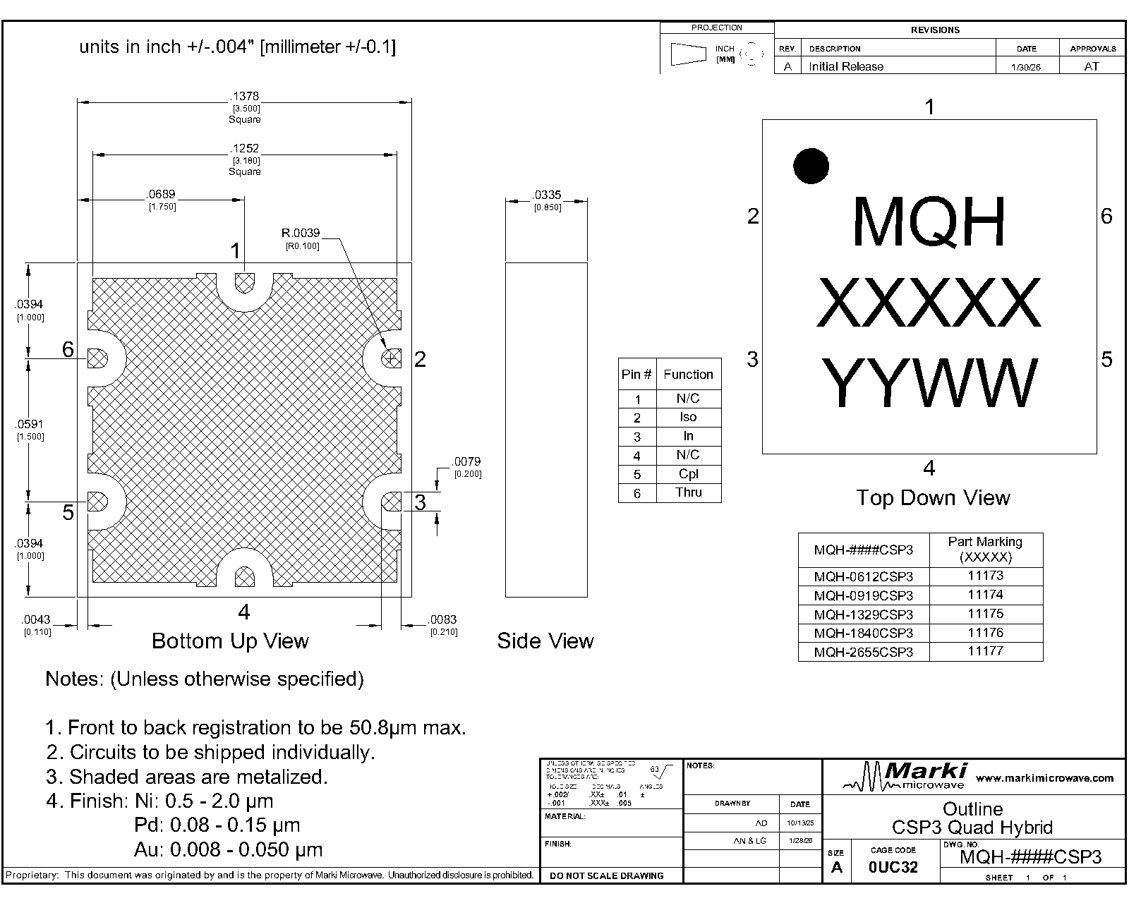
| Dimensions | - | 3.50 x 3.50 mm |
| Moisture Sensitivity Level | - | MSL 1 |
MQH-1329CSP3
MMIC 13 - 29 GHz 90° Hybrid Coupler
| Parameter | Port Configuration | Test Conditions | Minimum Frequency (GHz) | Maximum Frequency (GHz) | Min | Typ | Max | Unit |
|---|---|---|---|---|---|---|---|---|
| Amplitude Balance | C | Configuration C | 13 | 29 | - | 0.6 | - | dB |
| Excess Insertion Loss | C | Configuration C | 13 | 29 | - | 0.7 | - | dB |
| Impedance | - | All Ports | 13 | 29 | - | 50 | - | Ω |
| Isolation | C | Configuration C | 13 | 29 | - | 23 | - | dB |
| Mean Coupling | - | - | 13 | 29 | - | 3 | - | dB |
| Nominal Phase Shift | C | Configuration C | 13 | 29 | - | 90 | - | ° |
| Return Loss | - | All Ports | 13 | 29 | - | 22 | - | dB |
| Phase Balance | C | Configuration C | 13 | 29 | - | 0.6 | - | ° |
Excess Insertion Loss = Input to Output Insertion Loss - 3dB
MQH-1329CSP3
MMIC 13 - 29 GHz 90° Hybrid Coupler
Typical performance plots shown for port configuration C. Performance may vary in alternate configurations.
%20vs%20Frequency.png)
%20vs%20Frequency.png)
%20vs%20Frequency.png)
%20vs%20Frequency.png)
%20vs%20Frequency.png)
%20vs%20Frequency%20All%20Configurations.png)
%20vs%20Frequency.png)
%20vs%20Frequency%20All%20Configurations.png)
MQH-1329CSP3
MMIC 13 - 29 GHz 90° Hybrid Coupler
%20vs%20Frequency.png)
MQH-1329CSP3
MMIC 13 - 29 GHz 90° Hybrid Coupler
MQH-1329CSP3
MMIC 13 - 29 GHz 90° Hybrid Coupler
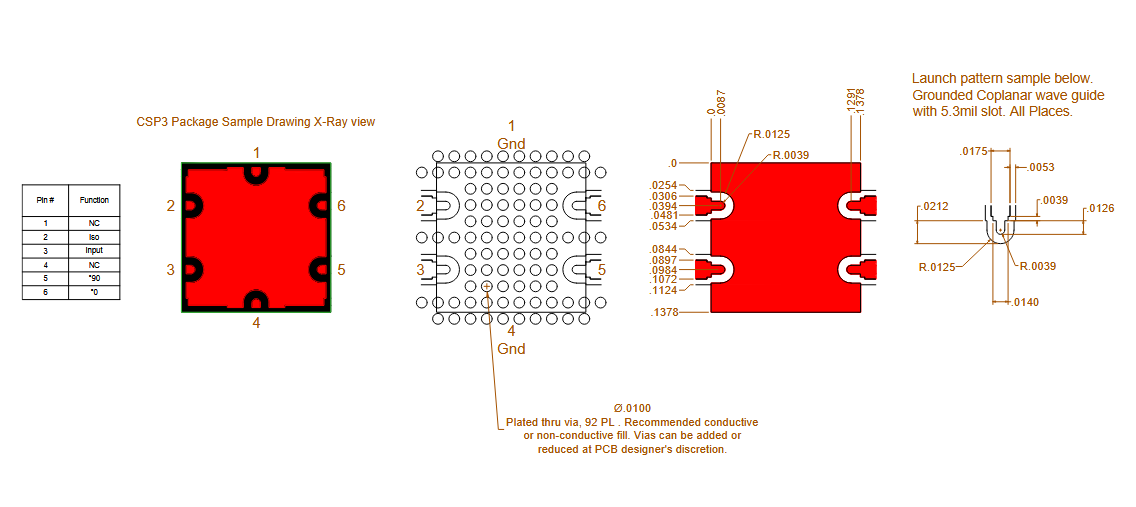
Download : Footprint Drawing
MQH-1329CSP3
MMIC 13 - 29 GHz 90° Hybrid Coupler