Port Diagram
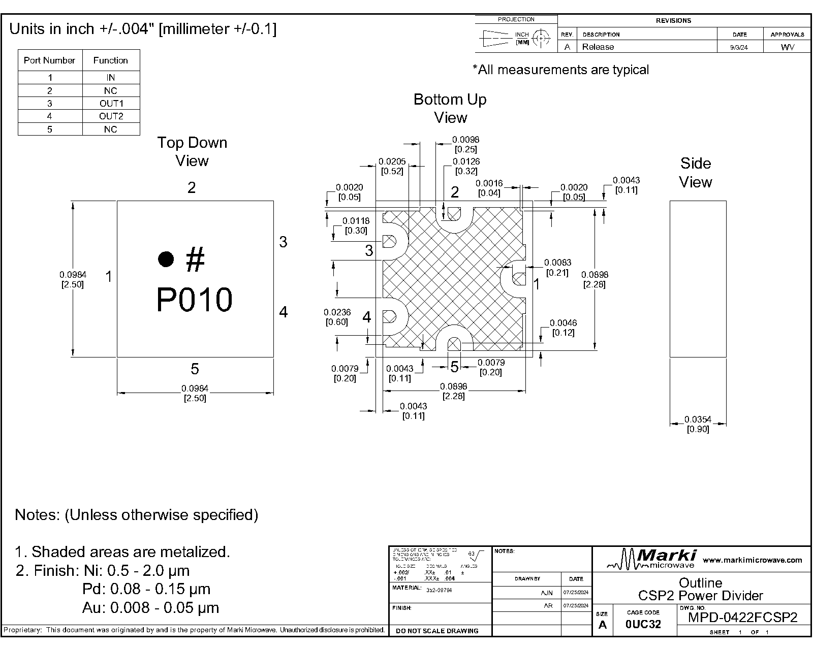
A bottom-up view of the MPD-0422FCSP2 package outline drawing is shown below. The MMIC Power dividers are passive reciprocal devices allowing either power splitting or power combining.

Sales: 408-778-9952 | General: 408-778-4200 | Fax: 408-778-4300
Sales & Customer Support: [email protected]
Tech Support: [email protected]
The MPD-0422FCSP2 is a small footprint MMIC 4-22 GHz 2-Way power divider/power splitter featuring high 24 dB isolation and low 0.7 dB insertion loss in our compact CSP2 chip scale package. It is much smaller than a printed PCB Wilkinson Power Divider/Combiner. It can be used as an equal amplitude/phase power splitter or a power combiner with excellent isolation. Tight fabrication tolerances result in less unit-to-unit variation than traditional power divider technologies, allowing for accurate simulations using the provided S3P file taken from measured production units. The MPD-0422FCSP2 features front port outputs opposite to the common port. For side port outputs, refer to the MPD-0422SCSP2. The 2.5 mm CSP2 package enables extreme miniaturization of SMT footprint making the MPD-0422FCSP2 ideal for applications prioritizing low SWaP.


| Part Number | Description | Package | Green Status | Product Lifecycle | Export Classification |
|---|---|---|---|---|---|
| MPD-0422FCSP2 | 4 - 22 GHz MMIC 2-Way Wilkinson Power Divider/Power Splitter, Front Ports | CSP2 | REACH RoHS | Released | EAR99 |
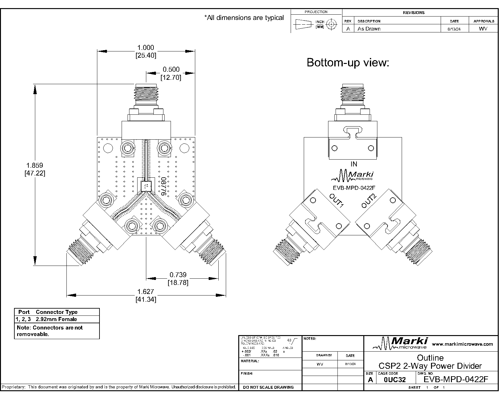
| EVB-MPD-0422F | Evaluation Board, 4 - 22 GHz MMIC 2-Way Wilkinson Power Divider/Power Splitter, Front Ports | EVB | RoHS REACH | Released | EAR99 |
| Part Number | Description | Package | Green Status | Product Lifecycle | Export Classification |
|---|---|---|---|---|---|
| MPD-0422FCSP2 | 4 - 22 GHz MMIC 2-Way Wilkinson Power Divider/Power Splitter, Front Ports | CSP2 | REACH RoHS | Released | EAR99 |
| EVB-MPD-0422F | Evaluation Board, 4 - 22 GHz MMIC 2-Way Wilkinson Power Divider/Power Splitter, Front Ports | EVB | RoHS REACH | Released | EAR99 |
MPD-0422FCSP2
4 - 22 GHz MMIC 2-Way Wilkinson Power Divider/Power Splitter, Front Ports
| Revision Code | Revision Date | Comment |
|---|---|---|
| - | 2024-09-09 | Initial Release |
| A | 2025-04-28 | Updated Moisture Sensitivity from MSL3 to MSL1 |
| B | 2025-05-07 | Power Handling Added |
| C | 2025-12-17 | Power Handling Updated |
MPD-0422FCSP2
4 - 22 GHz MMIC 2-Way Wilkinson Power Divider/Power Splitter, Front Ports
A bottom-up view of the MPD-0422FCSP2 package outline drawing is shown below. The MMIC Power dividers are passive reciprocal devices allowing either power splitting or power combining.
| Port | Function | Description | DC Equivalent Circuit |
|---|---|---|---|
| Ground Paddle | Gnd | Ground paddle should be connected to RF ground |  |
| Pin 1 | Common | Pin 1 is the common input/output pin. It is DC short to Pin 3 and Pin 4 and open to ground. |  |
| Pin 3 | Input/Output 1 | Pin 3 is an input/output pin. It is DC short to the common and Pin 4 and open to ground. | |
| Pin 4 | Input/Output 2 | Pin 4 is an input/output pin. It is DC short to the common and Pin 3 and open to ground. | |
MPD-0422FCSP2
4 - 22 GHz MMIC 2-Way Wilkinson Power Divider/Power Splitter, Front Ports
The Absolute Maximum Ratings indicate limits beyond which damage may occur to the device. If these limits are exceeded, the device may be inoperable or have a reduced lifetime.
| Parameter | Maximum Rating | Unit |
|---|---|---|
| DC Current | 40 | mA |
| Maximum Operating Temperature | 100 | °C |
| Maximum Storage Temperature | 125 | °C |
| Minimum Operating Temperature | -55 | °C |
| Minimum Storage Temperature | -65 | °C |
| RF Power Handling as a Power Divider 1 | 10 | W |
[1] Power handling was tested increasing RF power at 12 GHz
| Parameter | Details | Rating |
|---|---|---|
| Dimensions | - | 2.50 x 2.50 mm |
| Moisture Sensitivity Level | - | MSL 1 |
MPD-0422FCSP2
4 - 22 GHz MMIC 2-Way Wilkinson Power Divider/Power Splitter, Front Ports
The electrical specifications apply at TA=+25°C in a 50Ω system. Min and Max limits are guaranteed at TA=+25°C.
| Parameter | Test Conditions | Minimum Frequency (GHz) | Maximum Frequency (GHz) | Min | Typ | Max | Unit |
|---|---|---|---|---|---|---|---|
| Amplitude Balance | - | 4 | 22 | - | 0.12 | - | dB |
| Common Port Return Loss | - | 4 | 22 | - | 23 | - | dB |
| Excess Insertion Loss 1 | - | 4 | 18 | - | 0.66 | - | dB |
| Excess Insertion Loss 2 | - | 18 | 22 | - | 1.04 | - | dB |
| Impedance | - | 4 | 22 | - | 50 | - | Ω |
| Isolation | - | 6 | 22 | - | 24 | - | dB |
| Isolation | - | 4 | 6 | - | 17 | - | dB |
| Nominal Phase Shift | - | 4 | 22 | - | 0 | - | ° |
| Nominal Power Splitting | - | 4 | 22 | - | 3 | - | dB |
| Output Return Loss | - | 4 | 22 | - | 22 | - | dB |
| Phase Balance | - | 4 | 22 | - | 0.15 | - | ° |
[1][2] Excess Insertion Loss is loss in addition to power splitting loss, calculated as (Common Port to Output Port Insertion Loss) – (Power splitting loss of 3 dB)
MPD-0422FCSP2
4 - 22 GHz MMIC 2-Way Wilkinson Power Divider/Power Splitter, Front Ports


Measured data is de-embedded from fixture using automatic fixture removal (AFR).
MPD-0422FCSP2
4 - 22 GHz MMIC 2-Way Wilkinson Power Divider/Power Splitter, Front Ports
MPD-0422FCSP2
4 - 22 GHz MMIC 2-Way Wilkinson Power Divider/Power Splitter, Front Ports
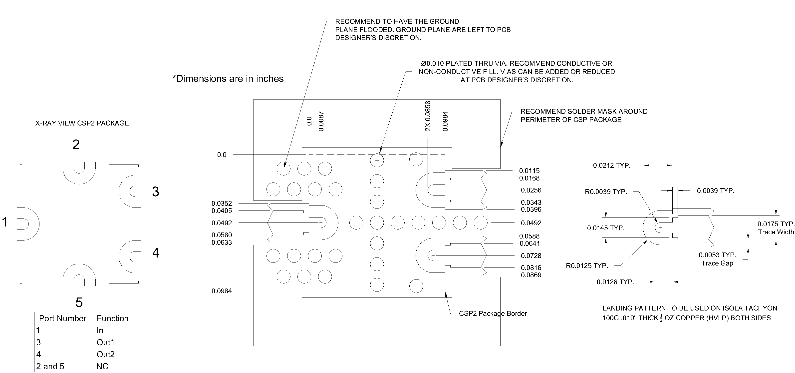
Download : Footprint Drawing
MPD-0422FCSP2
4 - 22 GHz MMIC 2-Way Wilkinson Power Divider/Power Splitter, Front Ports