Absolute Maximum Ratings
| Parameter | Maximum Rating | Unit |
|---|---|---|
| RF Power Handling , Average | 0.5 | W |
Sales: 408-778-9952 | General: 408-778-4200 | Fax: 408-778-4300
Sales & Customer Support: [email protected]
Tech Support: [email protected]
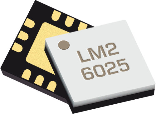
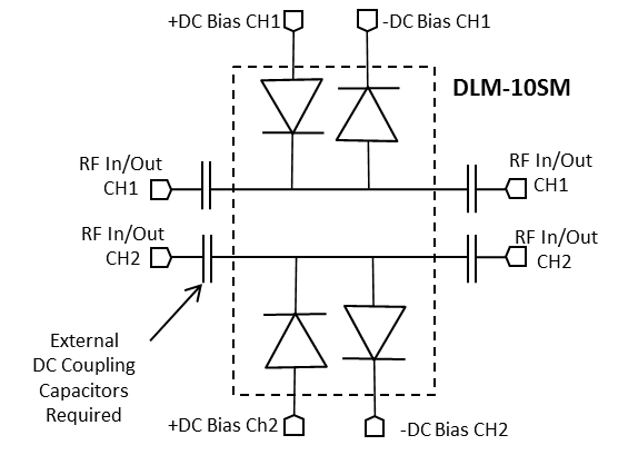
The DLM-10SM is a tunable, dual channel GaAs Schottky diode signal limiter featuring excellent IP3, insertion loss, and return loss. The limiting level is adjustable with an off-chip bias network, and the two channels can be used for differential or single-ended signals. The DLM-10SM is available in a lead-free, RoHS compliant QFN surface mount package and is compatible with standard leaded and lead-free PCB reflow soldering processes. The DLM-10SM is a superior alternative to discrete diode limiting options.

| Part Number | Description | Package | Green Status | Product Lifecycle | Export Classification |
|---|---|---|---|---|---|
| DLM-10SM | Tunable Differential Limiter | QFN | REACH RoHS | Released | EAR99 |
| EVAL-DLM-10 | Evaluation Board, Tunable Differential Limiter | EVAL | Consult Factory | Released | EAR99 |
DLM-10SM
Tunable Differential Limiter
| Revision Code | Revision Date | Comment |
|---|---|---|
| A | 2026-06-02 | Added Recovery Time and Spike Leakage |
DLM-10SM
Tunable Differential Limiter
| Parameter | Maximum Rating | Unit |
|---|---|---|
| RF Power Handling , Average | 0.5 | W |
| Parameter | Details | Rating |
|---|---|---|
| Dimensions | - | 3 x 3 mm |
| Moisture Sensitivity Level | - | MSL 1 |
DLM-10SM
Tunable Differential Limiter
| Parameter | Test Conditions | Minimum Frequency (GHz) | Maximum Frequency (GHz) | Min | Typ | Max | Unit |
|---|---|---|---|---|---|---|---|
| Spike Leakage | - | - | - | - | 0.1 | - | erg |
| Recovery Time | - | - | - | - | 8 | - | ns |
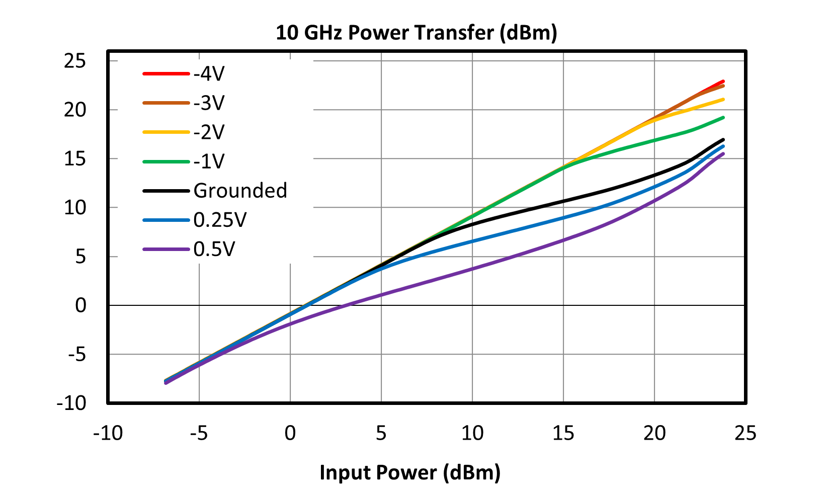
| Input P1dB | Grounded Bias | 0 | 10 | - | 10 | - | dBm |
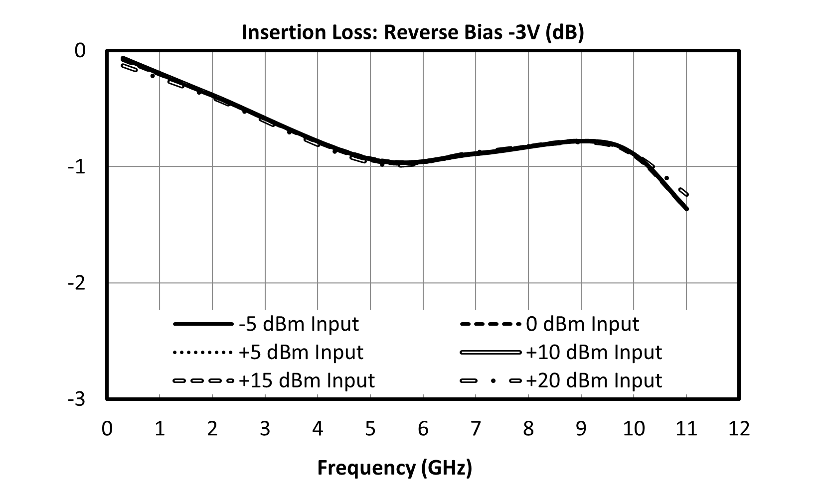
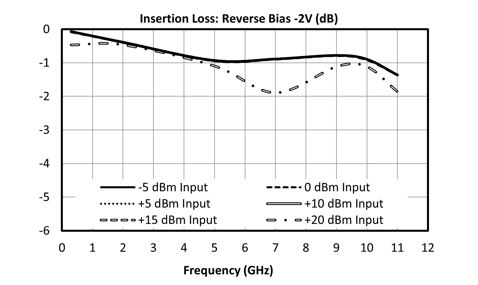
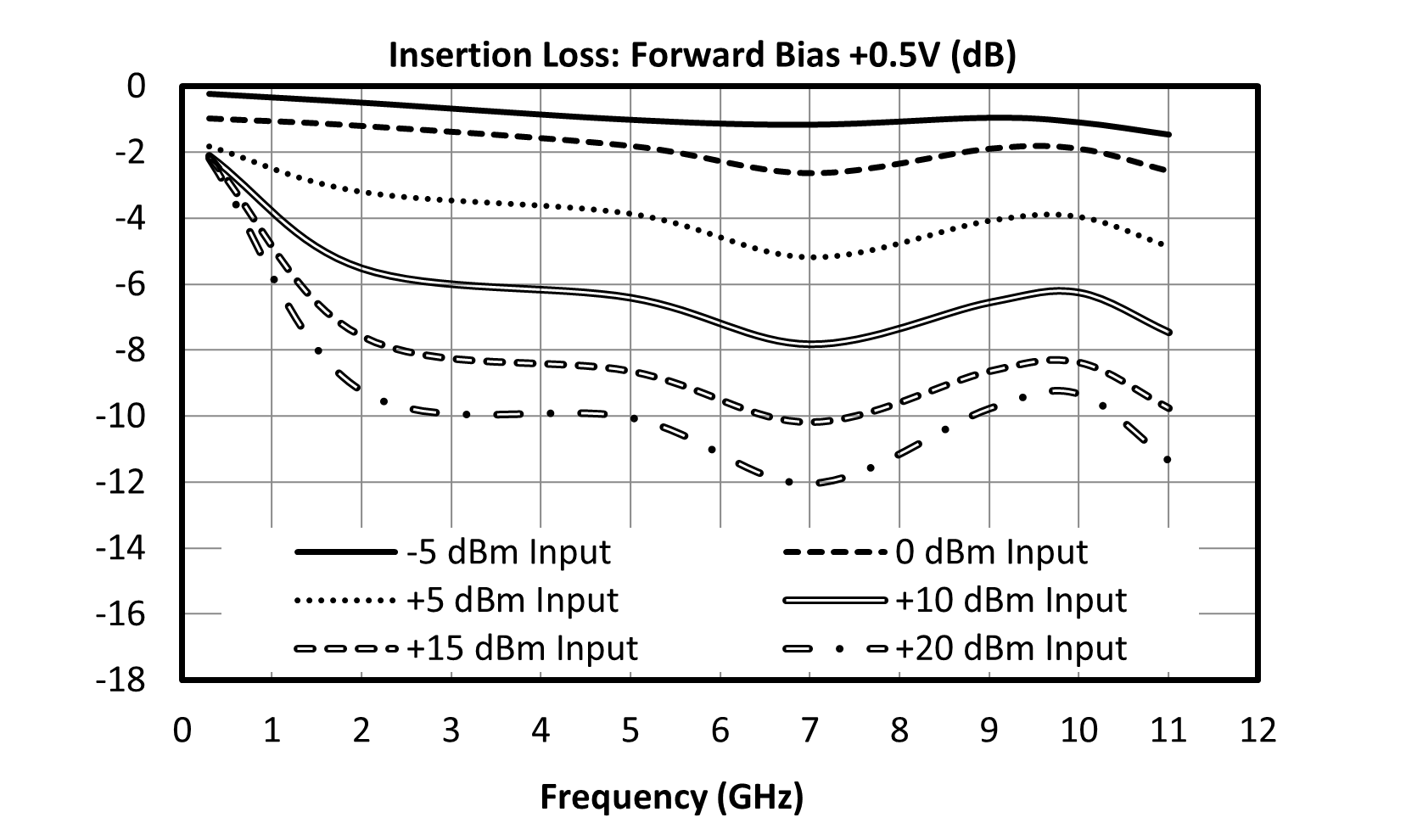
| Insertion Loss | +10dBm input power, grounded bias | 0 | 10 | - | 1.4 | - | dB |
| Insertion Loss | -10dBm input power, grounded bias | 0 | 10 | - | 0.75 | 1.5 | dB |
| Insertion Loss | +15dBm input power, grounded bias | 0 | 10 | - | 3.75 | - | dB |
| Return Loss | -10dBm to +9dBm, grounded bias | 0 | 10 | - | 20 | - | dB |
| Return Loss | +12dBm, grounded bias | 0 | 10 | - | 15 | - | dB |
| Parameter | Test Conditions | Minimum Frequency (GHz) | Maximum Frequency (GHz) | Min | Typ | Max | Unit |
|---|---|---|---|---|---|---|---|
| Spike Leakage | - | - | - | - | 0.1 | - | erg |
| Recovery Time | - | - | - | - | 8 | - | ns |
| Input P1dB | Grounded Bias | 0 | 10 | - | 10 | - | dBm |
| Insertion Loss | +10dBm input power, grounded bias | 0 | 10 | - | 1.4 | - | dB |
| Insertion Loss | -10dBm input power, grounded bias | 0 | 10 | - | 0.75 | 1.5 | dB |
| Insertion Loss | +15dBm input power, grounded bias | 0 | 10 | - | 3.75 | - | dB |
| Return Loss | -10dBm to +9dBm, grounded bias | 0 | 10 | - | 20 | - | dB |
| Return Loss | +12dBm, grounded bias | 0 | 10 | - | 15 | - | dB |
DLM-10SM
Tunable Differential Limiter


DLM-10SM
Tunable Differential Limiter


DLM-10SM
Tunable Differential Limiter


DLM-10SM
Tunable Differential Limiter
DLM-10SM
Tunable Differential Limiter
DLM-10SM
Tunable Differential Limiter
Download : Footprint Drawing

