| Parameter | Typ | Unit |
|---|---|---|
| Crossover Frequency | 24.66 | GHz |
Summary only – refer to the Electrical Specifications, Absolute Maximum Ratings, and Recommended Operating Range tables for complete details.

Sales: 408-778-9952 | General: 408-778-4200 | Fax: 408-778-4300
Sales & Customer Support: [email protected]
Tech Support: [email protected]
MDPX-00011CSP3
Passive MMIC 24.7 GHz Diplexer/Reflectionless filter
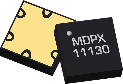
The MDPX-00011CSP3 is a MMIC surface mount high pass low pass diplexer featuring a 24.7 GHz crossover frequency. Passive GaAs MMIC technology allows production of smaller filter constructions that replace larger form factor circuit board constructions. Tight fabrication tolerances allow for less unit-to-unit variation than traditional filter technologies. The MDPX-00011CSP3 is available as a 3.5x3.5mm CSP3. Low unit to unit variation allows for accurate simulations using the provided S3P file taken from measured production units.

| Parameter | Typ | Unit |
|---|---|---|
| Crossover Frequency | 24.66 | GHz |
Summary only – refer to the Electrical Specifications, Absolute Maximum Ratings, and Recommended Operating Range tables for complete details.
| Part Number | Description | Package | Green Status | Product Lifecycle | Export Classification |
|---|---|---|---|---|---|
| MDPX-00011CSP3 | Passive MMIC 24.7 GHz Diplexer/Reflectionless filter | CSP3 | RoHS REACH | Released | EAR99 |
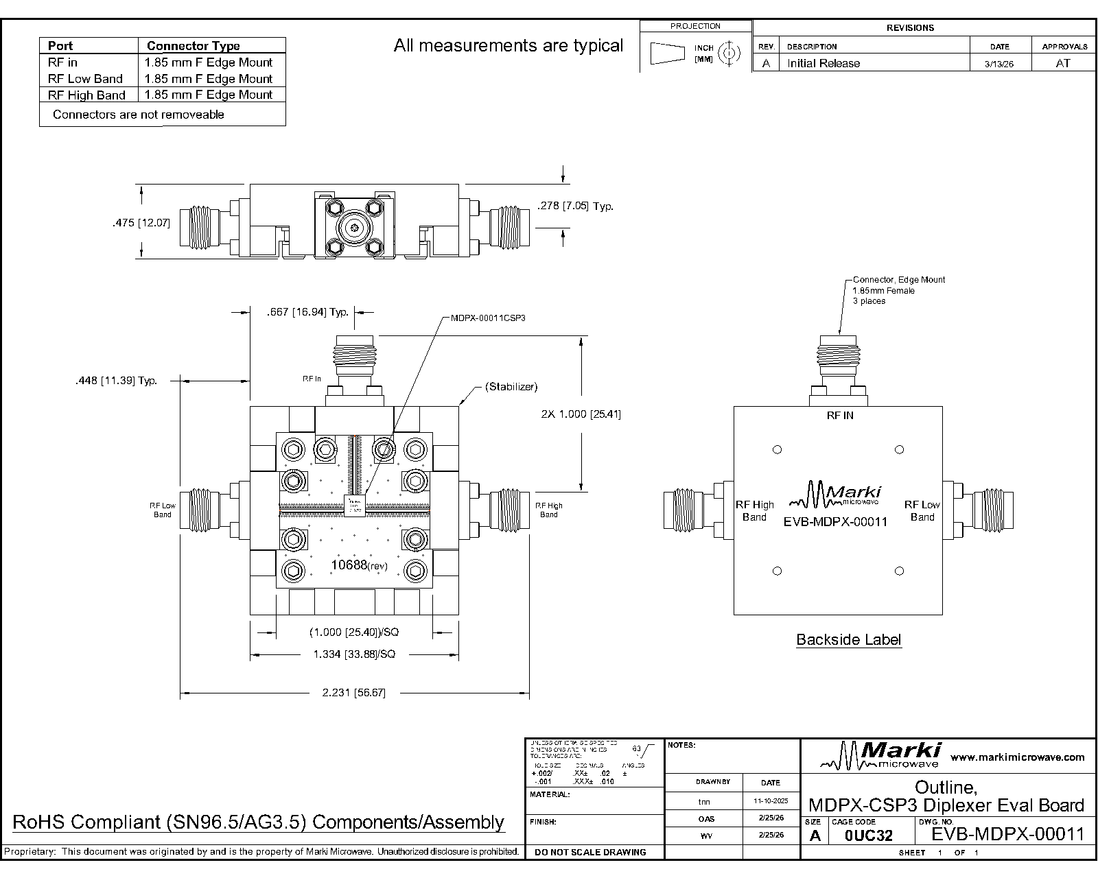
| EVB-MDPX-00011 | Evaluation Board, Passive MMIC 24.7GHz Diplexer/Reflectionless Filter | EVB | RoHS REACH | Released | EAR99 |
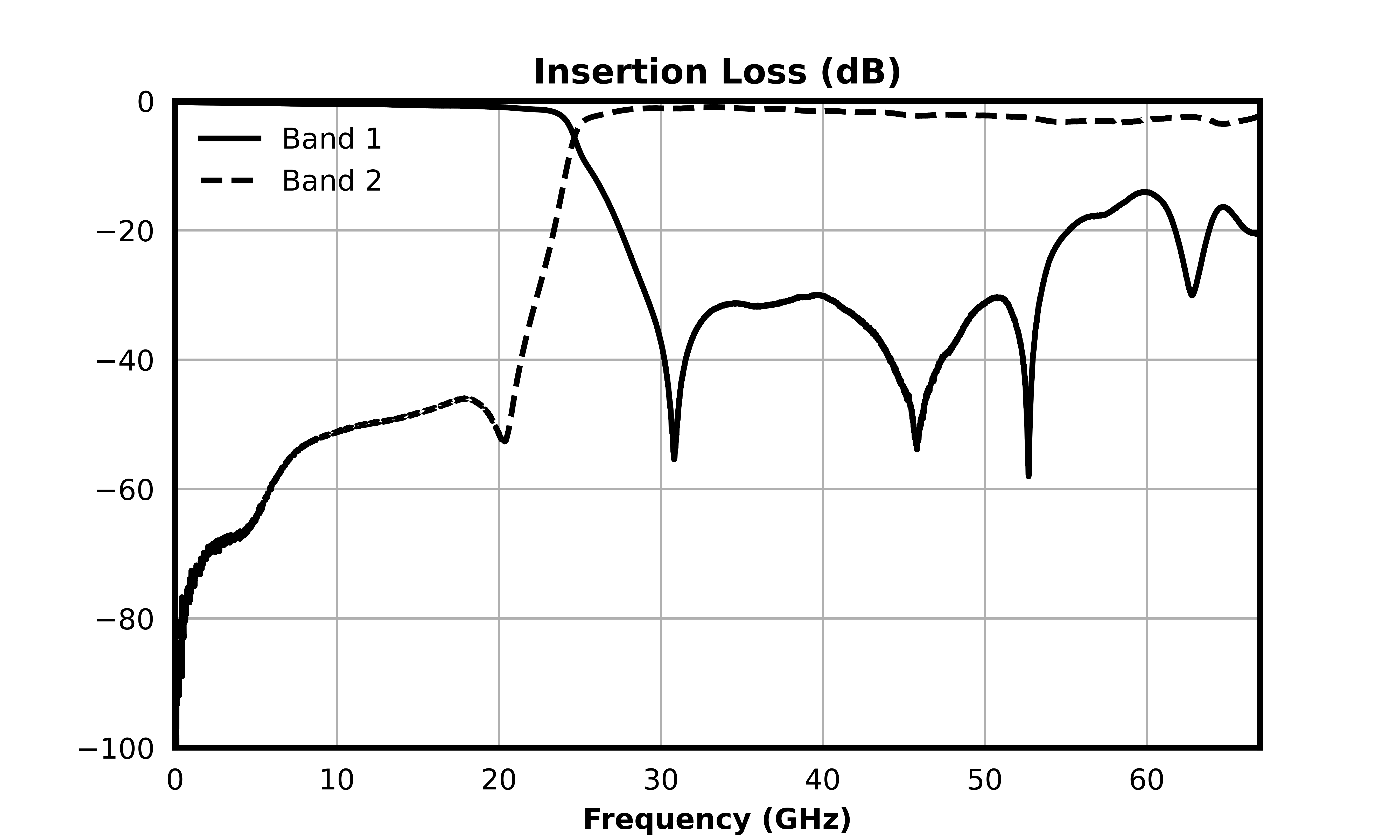
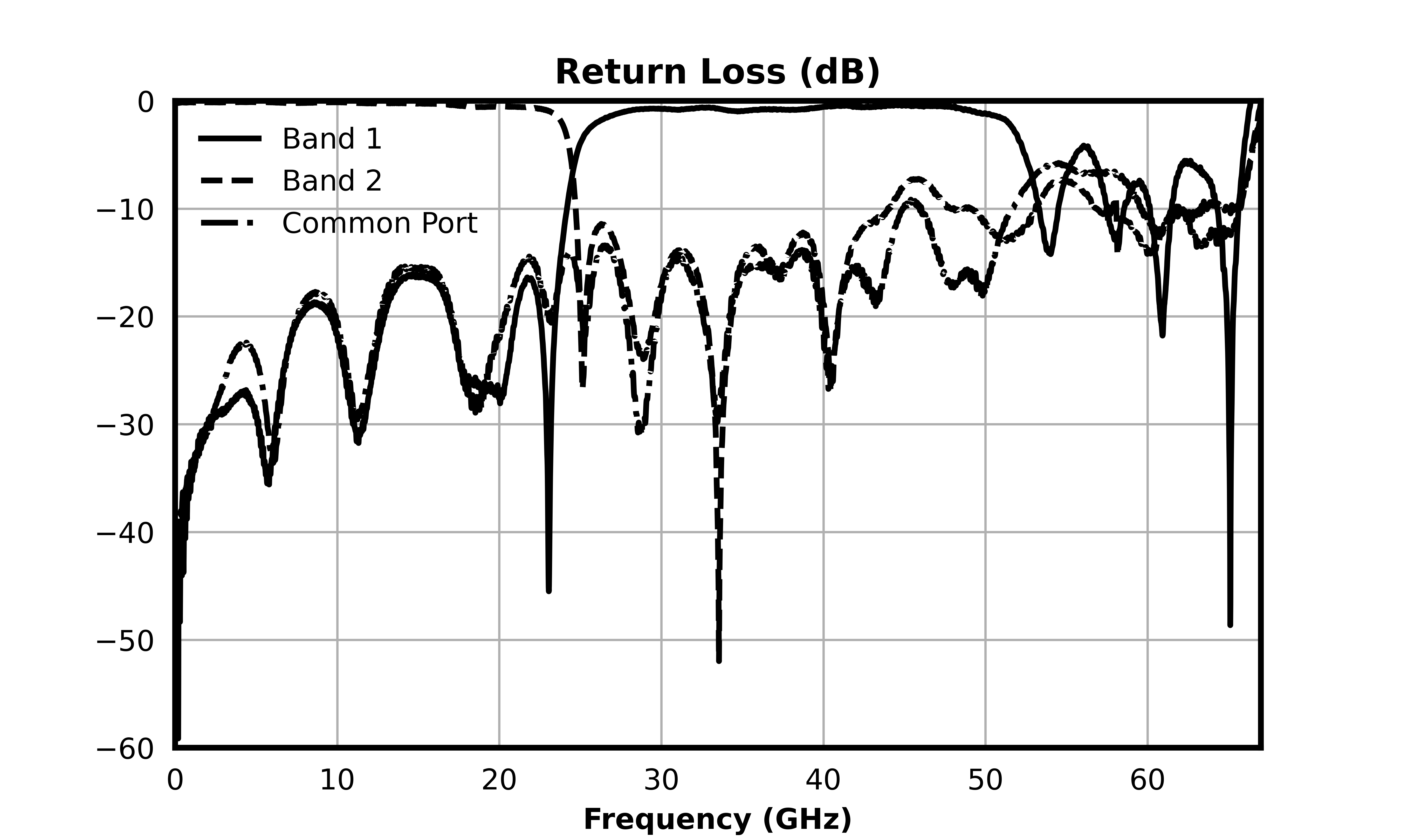
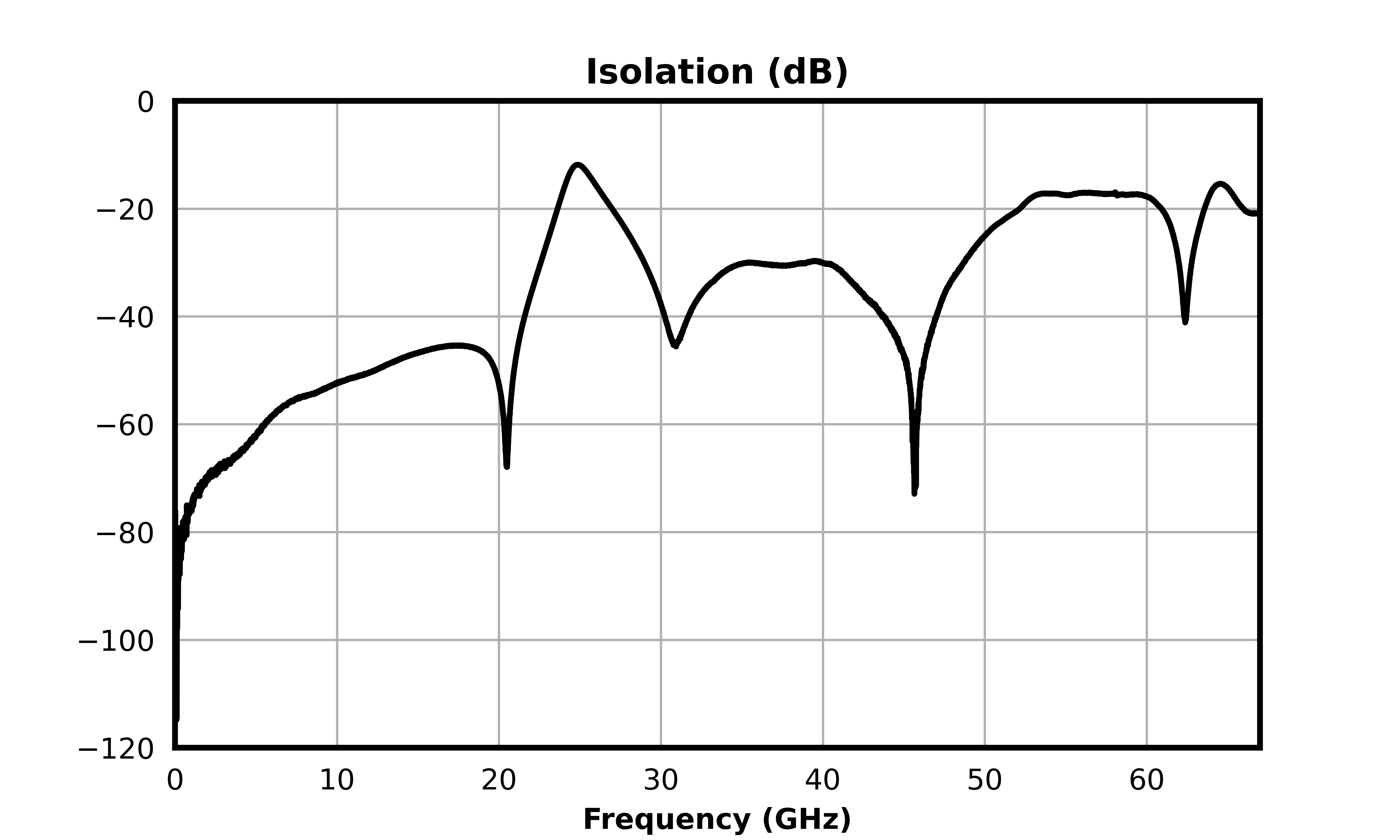
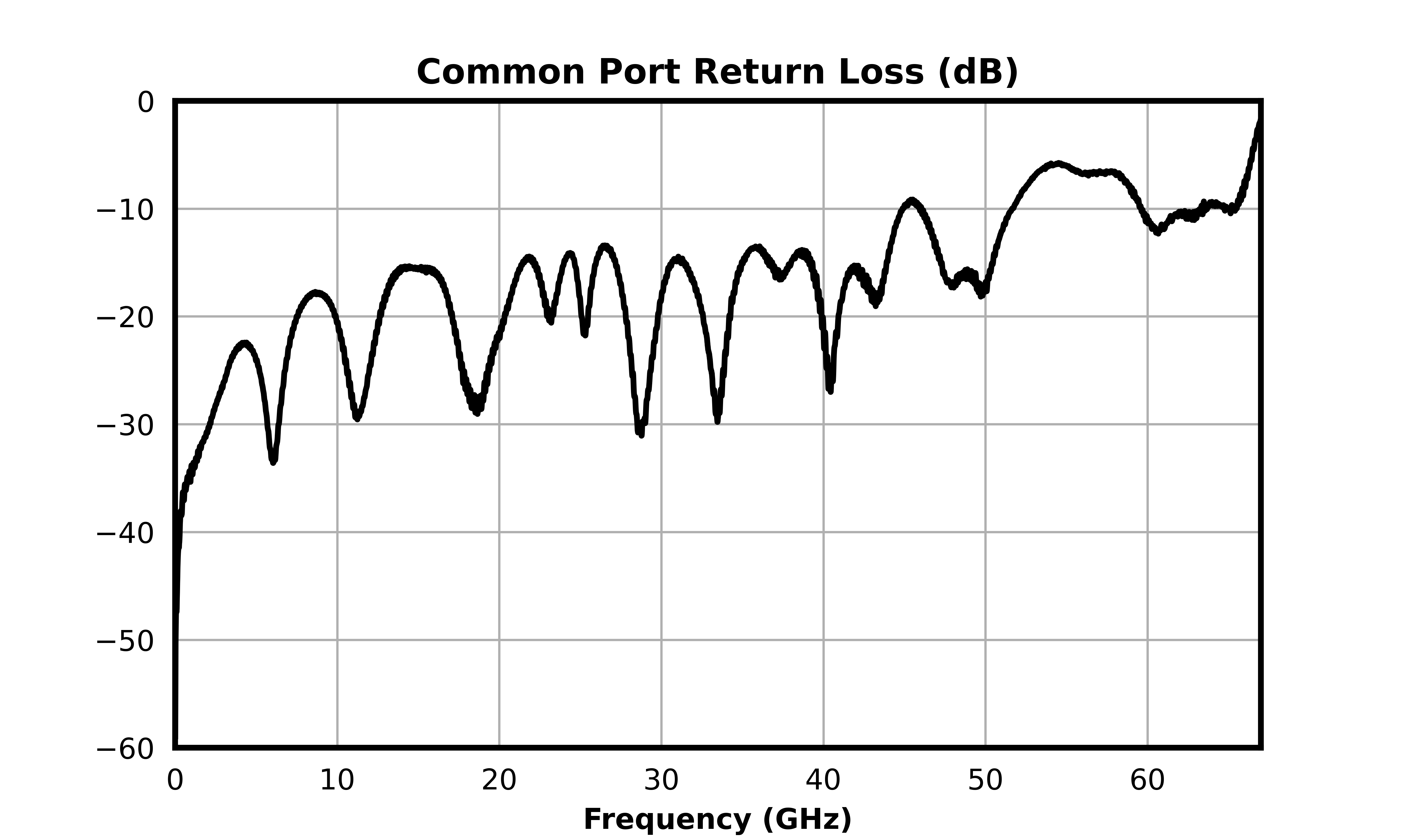
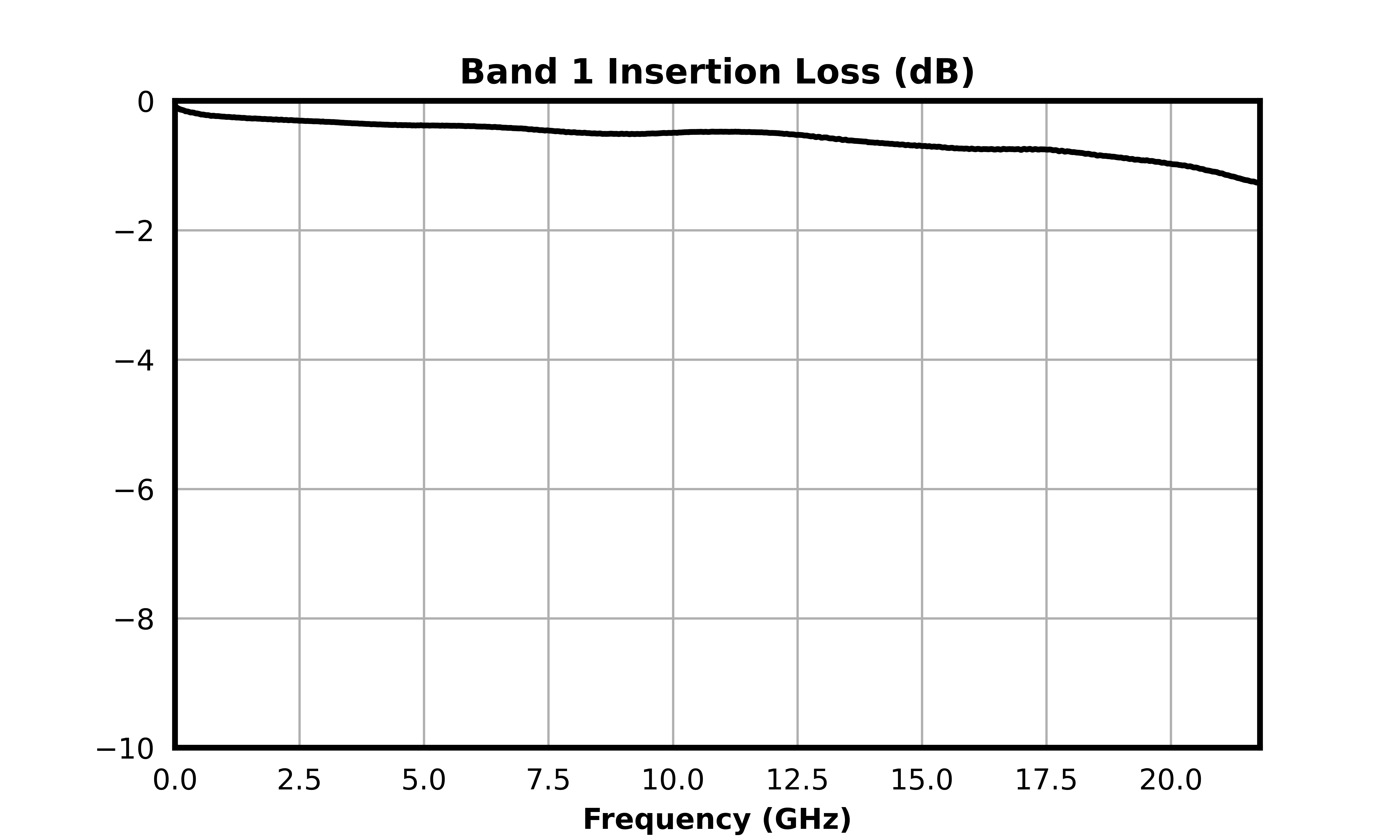
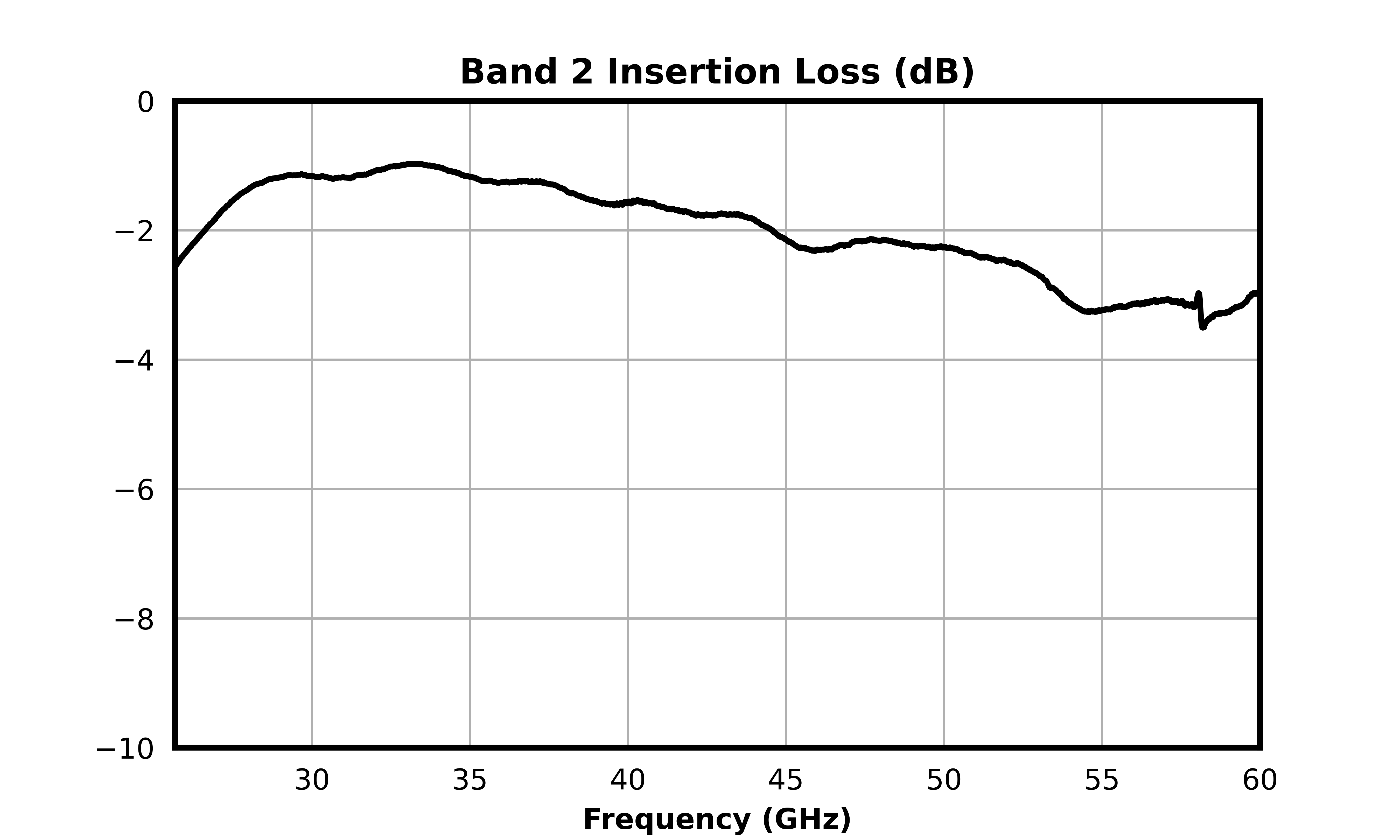
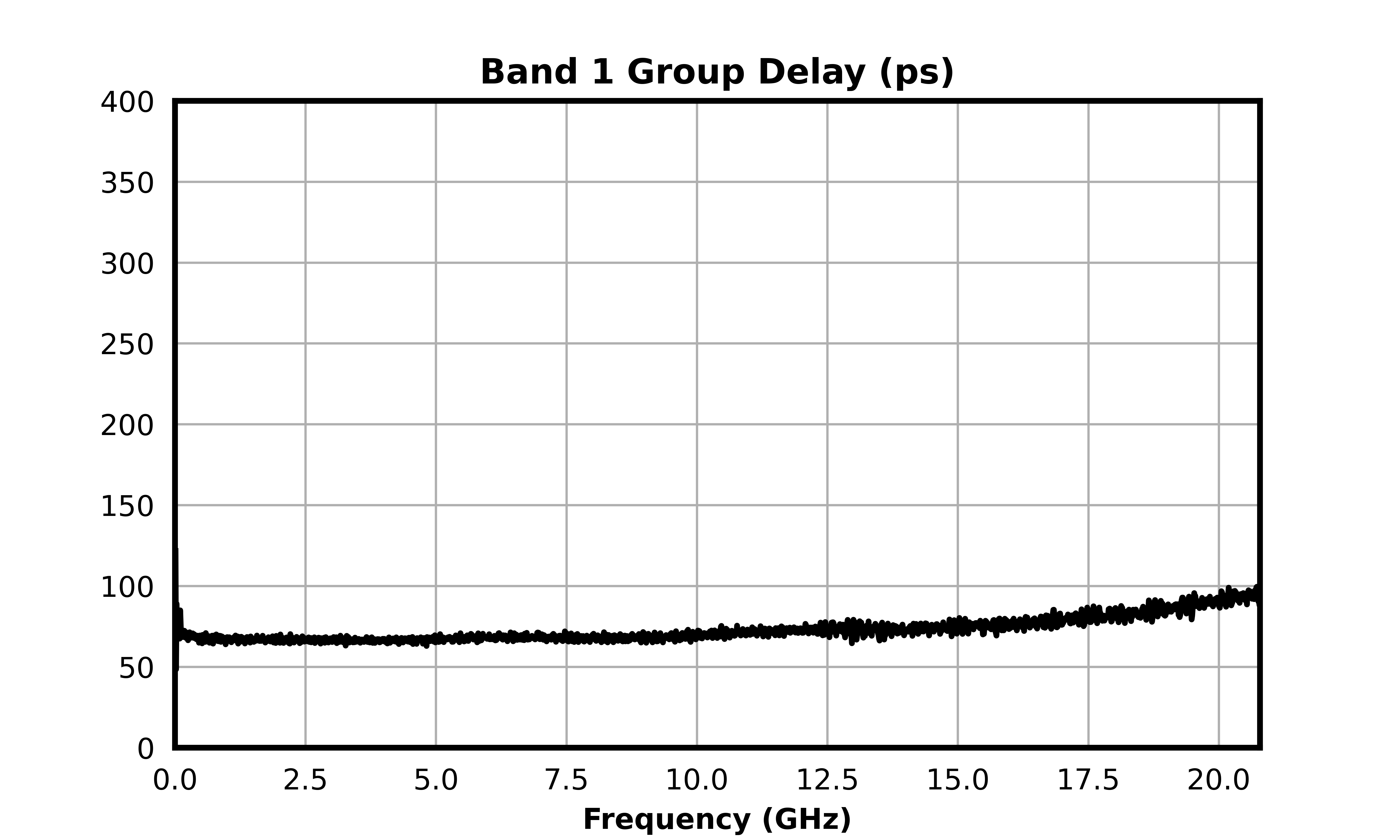
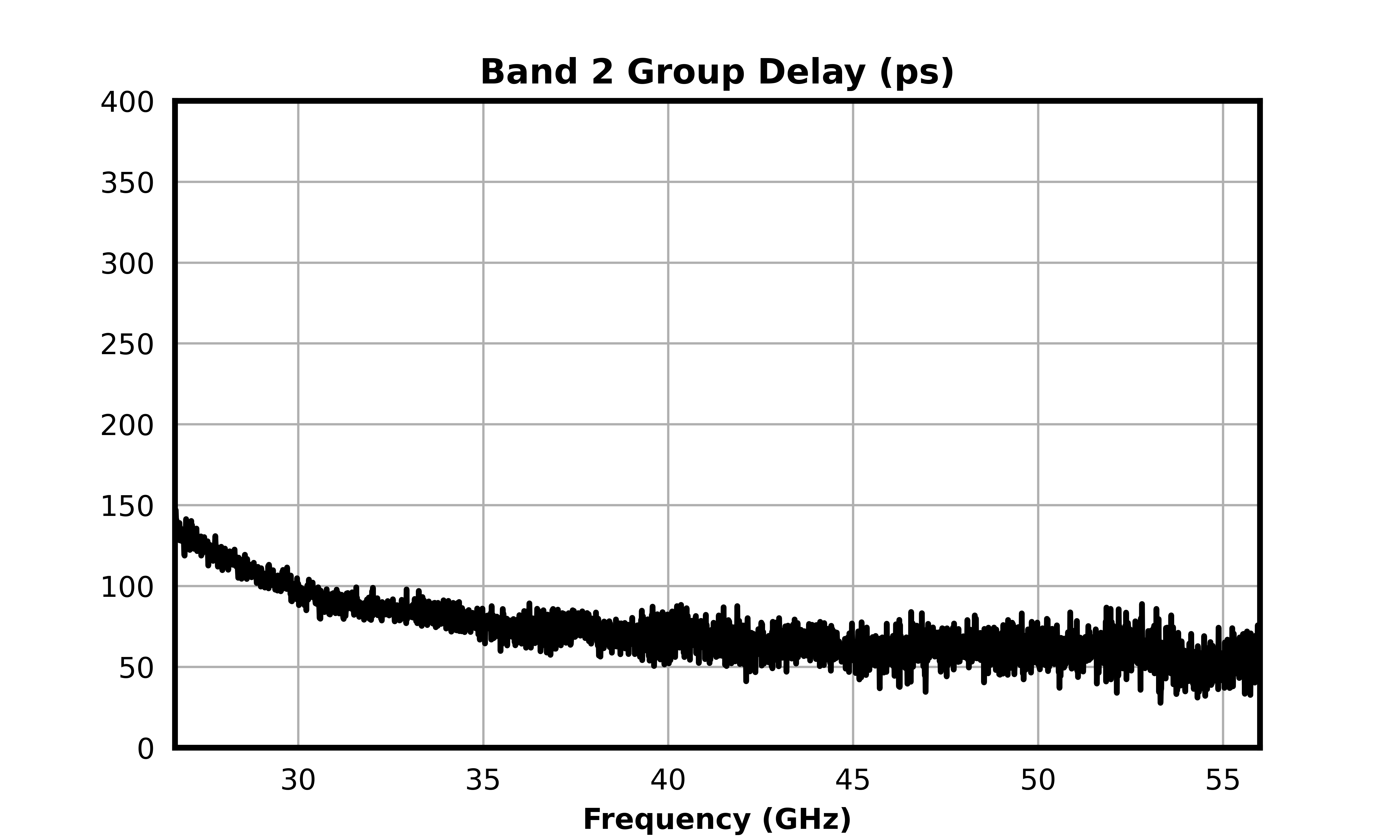
All measurements are de-embedded from the fixture with Automatic Fixture Removal (AFR).
| Parameter | Test Conditions | Minimum Frequency (GHz) | Maximum Frequency (GHz) | Min | Typ | Max | Unit |
|---|---|---|---|---|---|---|---|
| Band 1: 1 dBc Passband | Temp = 25°C | 0 | 20.79 | - | - | - | GHz |
| Band 1: 3 dBc Passband | Temp = 25°C | 0 | 24.16 | - | - | - | GHz |
| Band 1: 30 dBc Rejection Point | Temp = 25°C | 29.07 | 29.07 | - | - | - | GHz |
| Band 1: Return Loss | Temp = 25°C | 0 | 20.79 | - | 25.95 | - | dB |
| Band 1: Group Delay | Temp = 25°C | 0 | 20.79 | - | 70.41 | - | ps |
| Band 2: 1 dBc Passband | Temp = 25°C | 26.67 | 60 | - | - | - | GHz |
| Band 2: 3 dBc Passband | Temp = 25°C | 24.96 | 60 | - | - | - | GHz |
| Band 2: 30 dBc Rejection Point | Temp = 25°C | 22.28 | 22.28 | - | - | - | GHz |
| Band 2: Return Loss | Temp = 25°C | 26.67 | 60 | - | 12.49 | - | dB |
| Band 2: Group Delay | Temp = 25°C | 26.67 | 60 | - | 67.86 | - | ps |
| Crossover Frequency | Temp = 25°C | - | - | - | 24.66 | - | GHz |
| Crossover Isolation | Temp = 25°C | - | - | - | 12 | - | dB |
| Parameter | Maximum Rating | Unit |
|---|---|---|
| DC Current | 120 | mA |
| Maximum Operating Temperature | 100 | °C |
| Maximum Storage Temperature | 125 | °C |
| Minimum Operating Temperature | -55 | °C |
| Minimum Storage Temperature | -65 | °C |
| Parameter | Details | Rating |
|---|---|---|
| ESD | 250 to < 500 Volts | HBM Class 1A |
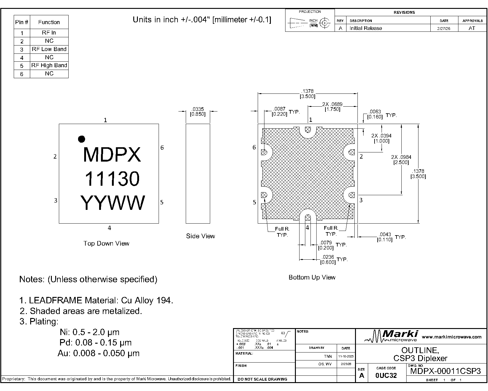
| Dimensions | - | 3.50 x 3.50 mm |
| Moisture Sensitivity Level | - | MSL 1 |
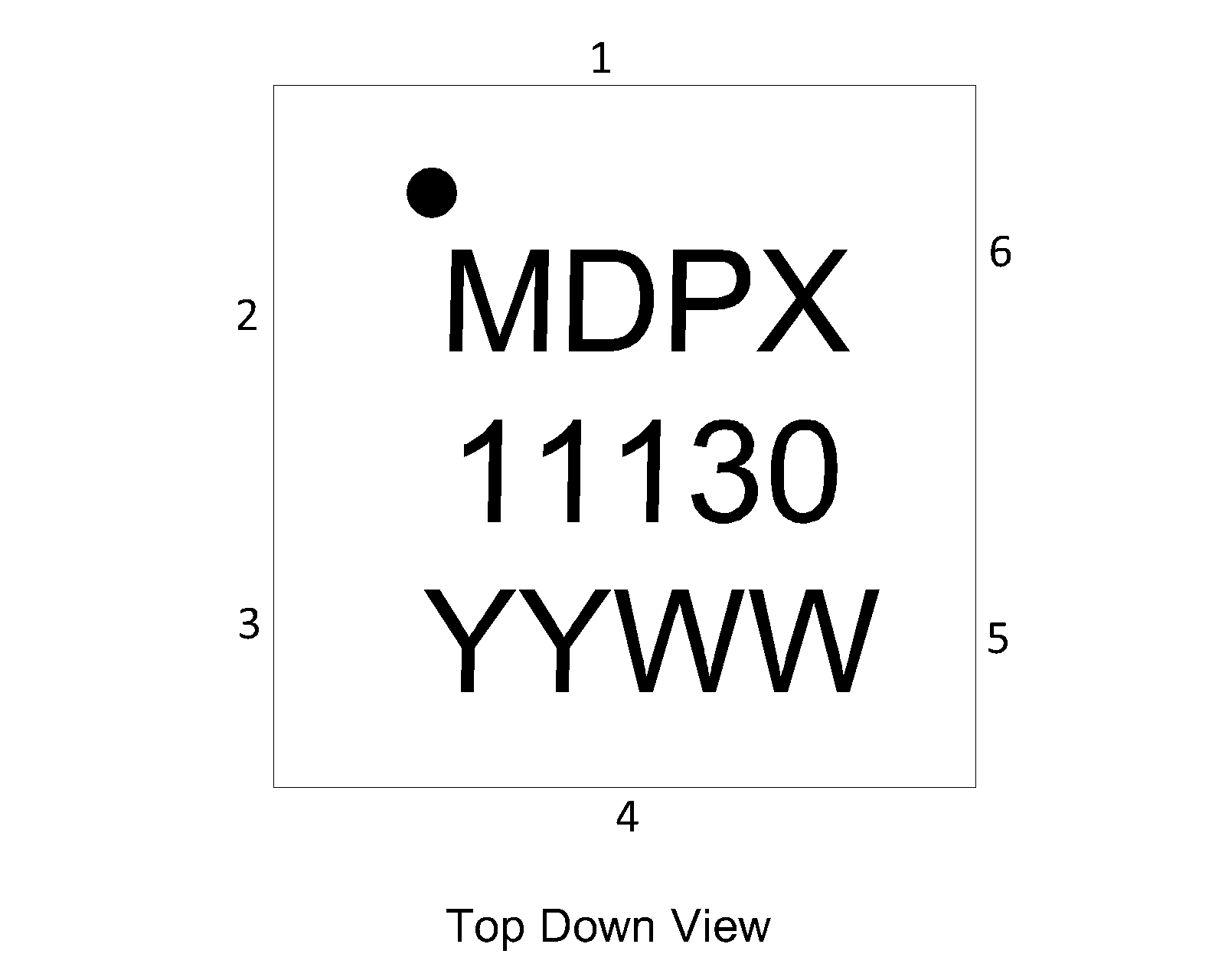
| Port | Function | Description | DC Equivalent Circuit |
|---|---|---|---|
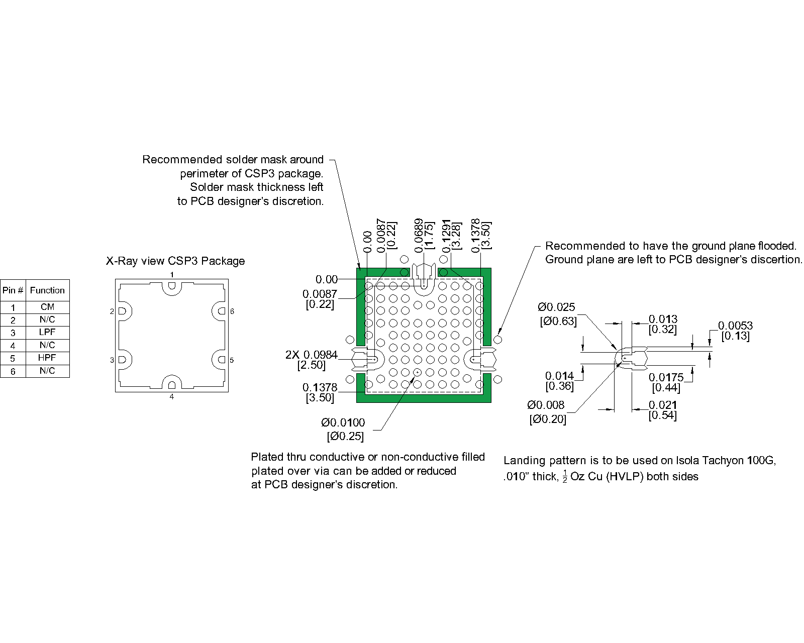
| Pin 1 | Common/Input | Pin 1 is DC short to Pin 3 and open to GND and Pin 5. |  |
| Pin 3 | RF Low Band | Pin 3 is DC short to Pin 1 and open to GND and Pin 5 | |
| Pin 5 | RF High Band | Pin 5 is DC open to Pin 1, Pin 3, and GND |  |
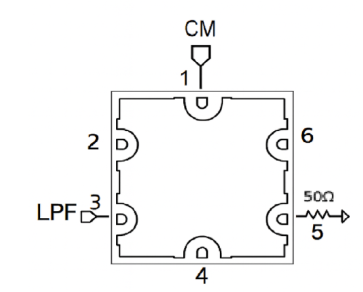
Terminating the High-Pass port (Pin 5) with 50 Ω enables one-way reflectionless low-pass filtering from the Common port (Pin 1) to the Low-Pass port (Pin 3).
Terminating the Low-Pass port (Pin 3) with 50 Ω enables one-way reflectionless high-pass filtering from the Common port (Pin 1) to the High-Pass port (Pin 5).
Download : Outline 2D Drawing
| Revision Code | Revision Date | Comment |
|---|---|---|
| - | 2026-08-12 | Initial Release |
MARKI MICROWAVE, LLC., (“MARKI”) PROVIDES TECHNICAL SPECIFICATIONS AND DATA (INCLUDING DATASHEETS), APPLICATION OR OTHER DESIGN ADVICE, WEB TOOLS, AND OTHER INFORMATION AND RESOURCES “AS IS” AND WITH ALL FAULTS. MARKI DISCLAIMS ALL WARRANTIES, EXPRESS OR IMPLIED, INCLUDING, WITHOUT LIMITATION, ANY IMPLIED WARRANTIES OF MERCHANTABILITY, FITNESS FOR A PARTICULAR PURPOSE, OR NON-INFRINGEMENT.
These resources are intended for developers skilled in the art designing with Marki products. You are solely responsible for (1) selecting the appropriate products for your application, (2) designing, validating, and testing your application, and (3) ensuring your application meets applicable standards and other requirements. Marki makes no guarantee regarding the suitability of its products for any particular purpose, nor does Marki assume any liability whatsoever arising out of your use or application of any Marki product.
Marki grants you permission to use these resources only for development of an application that uses Marki products. Other reproduction or use of these resources is strictly prohibited. No license is granted to any other Marki intellectual property or to any third-party intellectual property. Marki reserves the right to make changes to the product(s) or information contained herein without notice.
MARKI MICROWAVE, M wave logo, FastSwitch, and T3 MIXER are trademarks or registered trademarks of Marki Microwave, LLC. All other trademarks used are the property of their respective owners.
© 2026, Marki Microwave, LLC