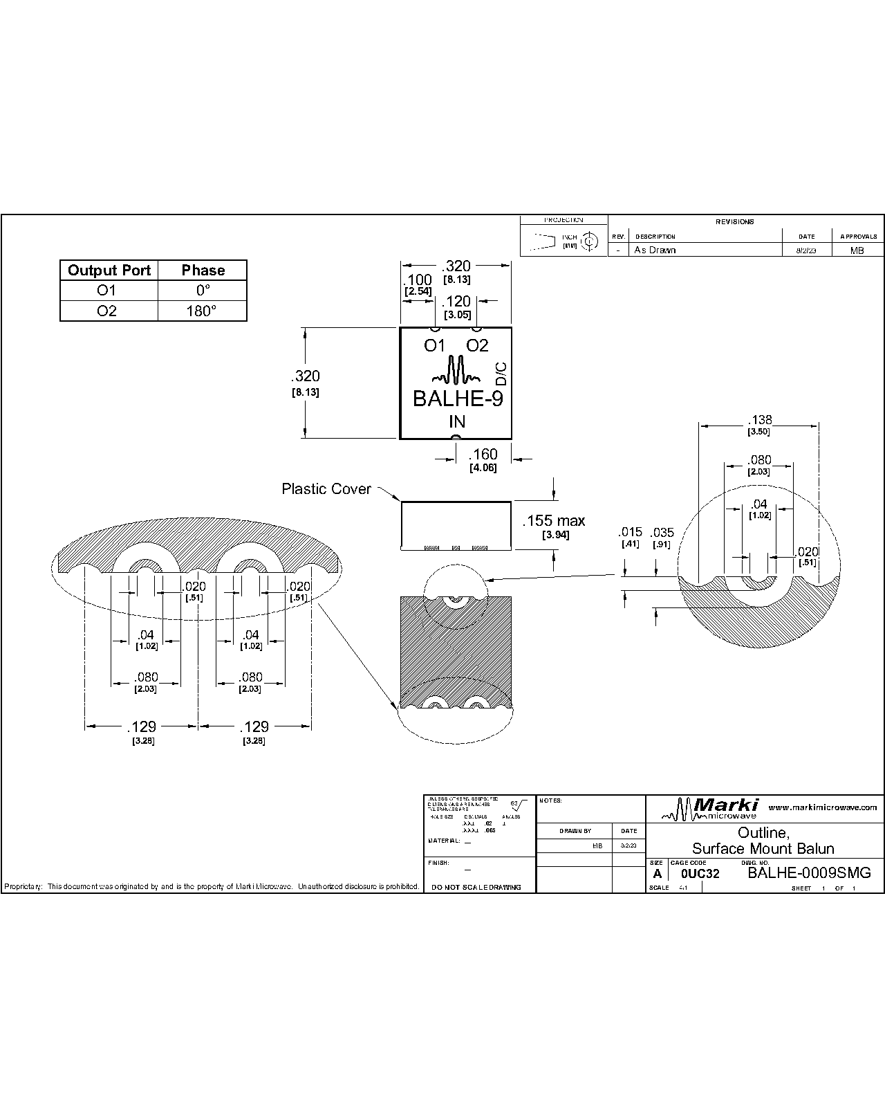
Port Diagram
A top-down view of the BALHE-0009SMG package outline drawing is shown below. Marki baluns are passive reciprocal devices allowing either single ended to differential or differential to single ended conversion.

END OF LIFE
Sales: 408-778-9952 | General: 408-778-4200 | Fax: 408-778-4300
Sales & Customer Support: [email protected]
Tech Support: [email protected]
The BALHE-0009SMG is a surface-mount broadband balun, hand-tuned for optimal phase and amplitude balance over 10 MHz to 9 GHz bandwidth. Designed for high volume production with cost optimization in mind, it serves as an excellent choice for analog to digital converters, balanced receivers, baseband digital modulations, and signal integrity enhancement. If lower frequency operation is required, the BALH-0009SMG offers performance down to 500 kHz in the same package.
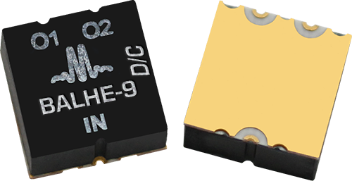
▪ 10MHz to 9GHz 1:1 Balun (Balanced to Unbalanced Transformer)
▪ Transforms 50 Ω single ended to 50 Ω differential/25 Ω single ended
▪ Tuned for Optimal Phase/Amplitude Balance

| Part Number | Description | Package | Green Status | Product Lifecycle | Export Classification | Recommended Replacement |
|---|---|---|---|---|---|---|
| BALHE-0009SMG | HIGH POWER SURFACE MOUNT BROADBAND BALUN | SMG | REACH RoHS | End of Life | EAR99 | BALH-0009SMG |
| Part Number | Description | Package | Green Status | Product Lifecycle | Export Classification | Recommended Replacement |
|---|---|---|---|---|---|---|
| BALHE-0009SMG | HIGH POWER SURFACE MOUNT BROADBAND BALUN | SMG | REACH RoHS | End of Life | EAR99 | BALH-0009SMG |
BALHE-0009SMG
HIGH POWER SURFACE MOUNT BROADBAND BALUN
| Revision Code | Revision Date | Comment |
|---|---|---|
| - | 2023-08-23 | Datasheet Initial Release |
| A | 2023-11-16 | Updated Power Handling |
| B | 2024-02-06 | Updated Phase Balance Max Specification |
BALHE-0009SMG
HIGH POWER SURFACE MOUNT BROADBAND BALUN
A top-down view of the BALHE-0009SMG package outline drawing is shown below. Marki baluns are passive reciprocal devices allowing either single ended to differential or differential to single ended conversion.
| Port | Function | Description | DC Equivalent Circuit |
|---|---|---|---|
| Common Port / In (Unbalanced) | RF Input | The common port is DC short to ground. |  |
| Out 1 / 0° Port (Balanced) | 0° Port | The 0° port is DC short to ground. | |
| Out 2/ 180° Port | 180° Port | The 180° port is DC short to ground | |
BALHE-0009SMG
HIGH POWER SURFACE MOUNT BROADBAND BALUN
| Parameter | Maximum Rating | Unit |
|---|---|---|
| RF Power Handling | 33 | dBm |
| Parameter | Details | Rating |
|---|---|---|
| Weight | Package name: SMG | 0.24g |
| Dimensions | - | 8.13 x 8.13mm |
| Moisture Sensitivity Level | - | MSL 1 |
BALHE-0009SMG
HIGH POWER SURFACE MOUNT BROADBAND BALUN
Specifications guaranteed from -55 to +100°C, measured in a 50Ω system.
| Parameter | Test Conditions | Minimum Frequency (GHz) | Maximum Frequency (GHz) | Min | Typ | Max | Unit |
|---|---|---|---|---|---|---|---|
| Impedance Ratio | - | 0.01 | 9 | - | 1:1 | - | - |
| Amplitude Balance | - | 0.01 | 9 | - | 0.1 | 1.6 | dB |
| Common Mode Rejection | - | 0.01 | 9 | 17 | 33 | - | dB |
| Common Port Return Loss | - | 0.01 | 9 | - | 12 | - | dB |
| Impedance | - | 0.01 | 9 | - | 50 | - | Ω |
| Insertion Loss as a Mode Converter | - | 0.01 | 9 | - | 2.5 | 5 | dB |
| Isolation | - | 0.01 | 9 | - | 7 | - | dB |
| Nominal Phase Shift | - | 0.01 | 9 | - | 180 | - | ° |
| Output Return Loss | - | 0.01 | 9 | - | 17 | - | dB |
| Phase Balance | - | 0.01 | 9 | - | 2 | 12 | ° |
BALHE-0009SMG
HIGH POWER SURFACE MOUNT BROADBAND BALUN
Electrical Specifications - Specifications guaranteed from -55 to +100°C, measured in a 50Ω system.
Mixed mode scattering parameters are used to characterize differential circuits. For baluns, this means that the 0° and 180° ports become a single 100Ω differential port and the common port remains the same 50Ω common port. The two-port s-parameters of the balun are then characterized based on differential (d), common mode (c), or single-ended (s) signals. Sds21 is the differential output response given a single ended input.


BALHE-0009SMG
HIGH POWER SURFACE MOUNT BROADBAND BALUN
Three port scattering parameters measured as three single-ended 50Ω ports showing relationship between any two ports.


BALHE-0009SMG
HIGH POWER SURFACE MOUNT BROADBAND BALUN
Download : Outline 2D Drawing Outline 3D Drawing Outline 3D STP
Substrate material is 8-mil thick Rogers 4003, 1 Oz Electrodeposited Cu. I/O Pads & Ground Plane Finish is Gold Flash, 5 to 10 µinches, over Electroplated Nickel, 100-200 µ-inches, over Cu.
BALHE-0009SMG
HIGH POWER SURFACE MOUNT BROADBAND BALUN
Download : Footprint Drawing
