Absolute Maximum Ratings
| Parameter | Maximum Rating | Unit |
|---|---|---|
| RF Power Handling | 1 | W |
END OF LIFE

Sales: 408-778-9952 | General: 408-778-4200 | Fax: 408-778-4300
Sales & Customer Support: [email protected]
Tech Support: [email protected]
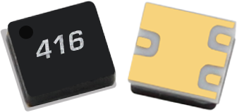
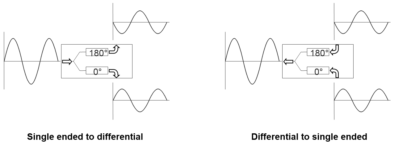
The BAL-0416SMG is a Surface Mount Microlithic™ balun. As with all Microlithic™ baluns, it features excellent amplitude balance, phase balance, and common mode rejection across a broad bandwidth and in a miniaturized form factor. It has significant isolation, reducing the reflection of unwanted common mode signals. The BAL-0416SMG is a lead free, RoHS compliant package compatible with standard leaded and lead-free solder reflows. SMA connectorized evaluation packages are available. The BAL-0416SMG is an excellent choice for balanced amplifiers, clock distribution, and higher order Nyquist sampling in analog to digital converters.
| Part Number | Description | Package | Green Status | Product Lifecycle | Export Classification | Recommended Replacement |
|---|---|---|---|---|---|---|
| BAL-0416SMG | Surface-Mount Broadband Balun | SMG | REACH RoHS | End of Life | EAR99 | MBAL-0220CSP2 |
| Part Number | Description | Package | Green Status | Product Lifecycle | Export Classification | Recommended Replacement |
|---|---|---|---|---|---|---|
| BAL-0416SMG | Surface-Mount Broadband Balun | SMG | REACH RoHS | End of Life | EAR99 | MBAL-0220CSP2 |
BAL-0416SMG
Surface-Mount Broadband Balun
| Revision Code | Revision Date | Comment |
|---|---|---|
| - | 2014-01-01 | Datasheet initial Release |
| A | 2016-01-01 | Typical Performance Plots Updated |
| B | 2019-10-01 | Mixed Mode Scattering Parameters added |
| C | 2020-07-01 | Specs table update |
| D | 2020-10-01 | Specs table update |
| E | 2021-10-01 | Plating spec update |
| F | 2024-07-31 | Product Lifecycle Update to EOL |
BAL-0416SMG
Surface-Mount Broadband Balun
| Port | Function | Description | DC Equivalent Circuit |
|---|---|---|---|
| 0° Port (Balanced) | 0° Port | The 0° port is DC short to the 180o port and passes through a resistor to ground. | 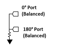 |
| 180° Port (Balanced) | 180° Port | The 180° port is DC short to the 0o port and passes through a resistor to ground. | |
| Common Port (Unbalanced) | RF Input | The common port is DC short to ground. | 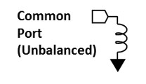 |
BAL-0416SMG
Surface-Mount Broadband Balun
| Parameter | Maximum Rating | Unit |
|---|---|---|
| RF Power Handling | 1 | W |
| Parameter | Details | Rating |
|---|---|---|
| Dimensions | - | 2.79 x 2.54 mm |
| Moisture Sensitivity Level | - | MSL 1 |
BAL-0416SMG
Surface-Mount Broadband Balun
Specifications guaranteed from -55 to +100°C, measured in a 50Ω system.
| Parameter | Test Conditions | Minimum Frequency (GHz) | Maximum Frequency (GHz) | Min | Typ | Max | Unit |
|---|---|---|---|---|---|---|---|
| Impedance Ratio | - | 4 | 16 | - | 2:1 | - | - |
| Amplitude Balance | - | 4 | 16 | - | 0.4 | 1 | dB |
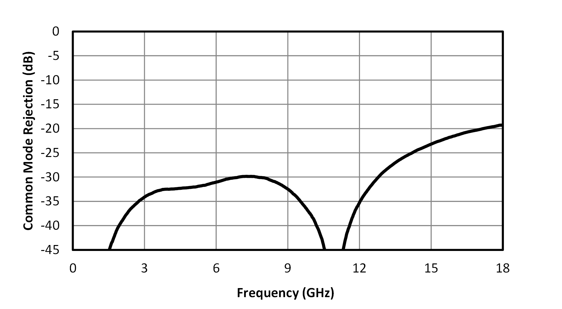
| Common Mode Rejection | - | 4 | 12 | 25 | 35 | - | dB |
| Common Mode Rejection | - | 12 | 16 | 15 | 26 | - | dB |
| Insertion Loss as a Mode Converter 1 | - | 4 | 16 | - | 3.3 | 5.5 | dB |
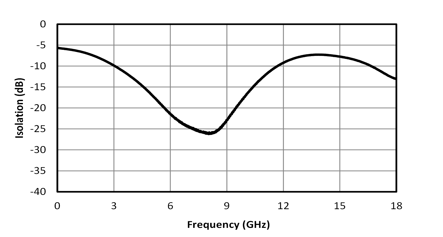
| Isolation | - | - | - | - | 15 | - | dB |
| Nominal Phase Shift | - | 4 | 16 | - | 180 | - | ° |
| Phase Balance | - | 12 | 16 | - | 6 | 15 | ° |
| Phase Balance | - | 4 | 12 | - | 1 | 5 | ° |
| VSWR | - | - | - | - | 2.5 | - | - |
| Parameter | Test Conditions | Minimum Frequency (GHz) | Maximum Frequency (GHz) | Min | Typ | Max | Unit |
|---|---|---|---|---|---|---|---|
| Impedance Ratio | - | 4 | 16 | - | 2:1 | - | - |
| Amplitude Balance | - | 4 | 16 | - | 0.4 | 1 | dB |
| Common Mode Rejection | - | 4 | 12 | 25 | 35 | - | dB |
| Common Mode Rejection | - | 12 | 16 | 15 | 26 | - | dB |
| Insertion Loss as a Mode Converter 1 | - | 4 | 16 | - | 3.3 | 5.5 | dB |
| Isolation | - | - | - | - | 15 | - | dB |
| Nominal Phase Shift | - | 4 | 16 | - | 180 | - | ° |
| Phase Balance | - | 12 | 16 | - | 6 | 15 | ° |
| Phase Balance | - | 4 | 12 | - | 1 | 5 | ° |
| VSWR | - | - | - | - | 2.5 | - | - |
[1] Includes fixture losses
BAL-0416SMG
Surface-Mount Broadband Balun
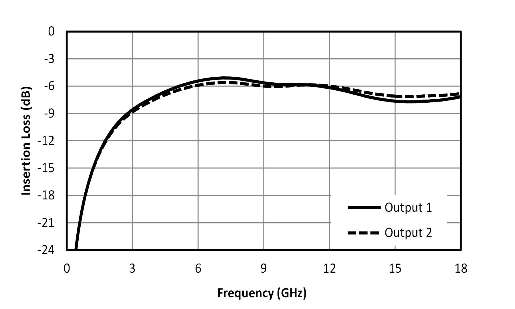
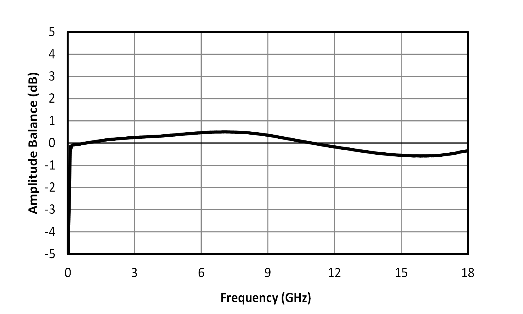
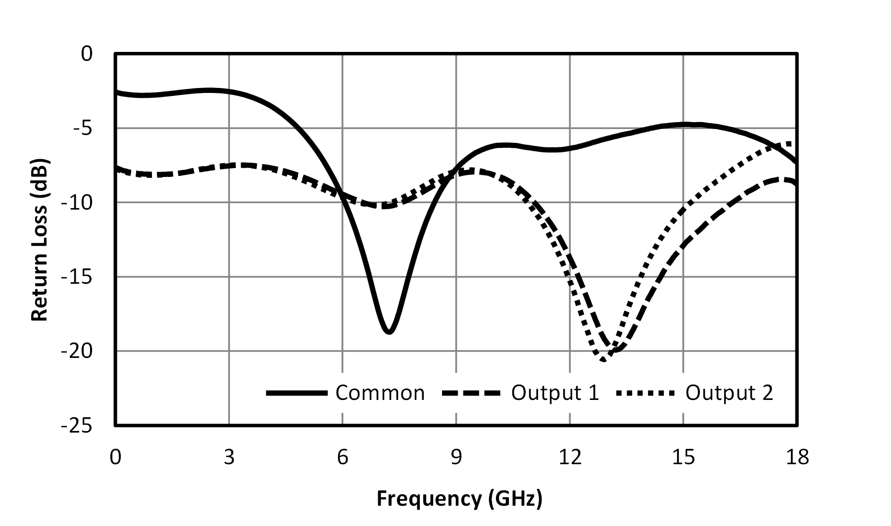
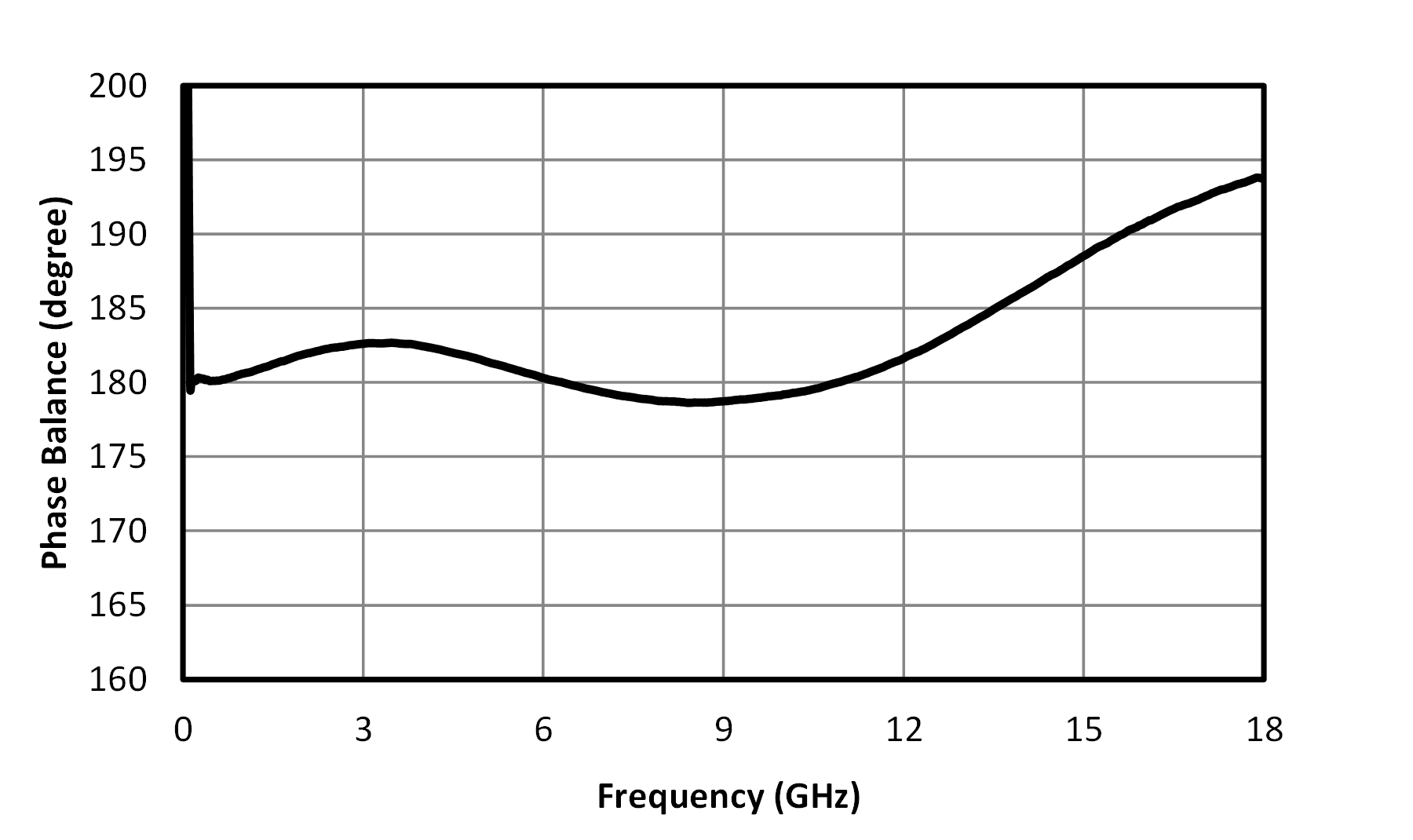
Three port scattering parameters measured as three single-ended 50Ω ports showing relationship between any two ports. For example: S21 and S31, often referred to as insertion loss of a balun, is the output response on ports 2 and 3 with an input stimulus on port 1.
1Includes test fixture loss. Results are not de-embedded.
BAL-0416SMG
Surface-Mount Broadband Balun
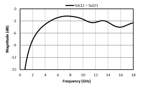
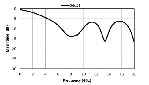
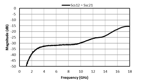
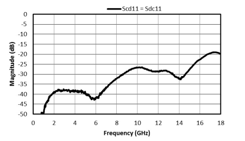
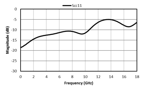
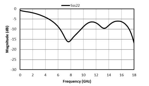
Mixed mode scattering parameters are used to characterize differential circuits. For baluns, this means that the 0° and 180° ports become a single 100Ω differential port and the common port remains the same 50Ω common port. The two-port s-parameters of the balun are then characterized based on differential (d), common mode (c), or single-ended (s) signals. For example: Scs12 is the Common output response given a single ended input.
BAL-0416SMG
Surface-Mount Broadband Balun