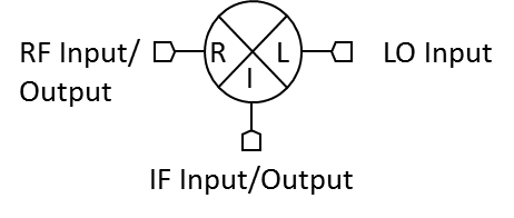
Port Diagram

NOT RECOMMENDED FOR NEW DESIGN
Sales: 408-778-9952 | General: 408-778-4200 | Fax: 408-778-4300
Sales & Customer Support: [email protected]
Tech Support: [email protected]
M8 mixers are hybrid assemblies that use a specially balanced technique to feature very low conversion loss and high isolations. M8 mixers have generally been replaced with MM1 mixers with superior performance, repeatability, and availability. M8 mixers are still used in legacy systems and are suitable for laboratory use.
N/A
| Part Number | Description | Package | Green Status | Product Lifecycle | Export Classification | Recommended Replacement |
|---|---|---|---|---|---|---|
| M8-0412NR | Double-Balanced 4 - 12 GHz Mixer | R | Consult Factory | End of Life | EAR99 | MM1-0312HS |
| M8-0412MR | Double-Balanced 4 - 12 GHz Mixer | R | Consult Factory | End of Life | EAR99 | MM1-0222LSMM1-0312HS |
| M8-0412LR | Double-Balanced 4 - 12 GHz Mixer | R | Consult Factory | Not Recommended for New Design | EAR99 | MM1-0222LSMM1-0312HS |
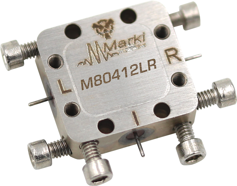
M8-0412LR
Double-Balanced 4 - 12 GHz Mixer
M8-0412LR
Double-Balanced 4 - 12 GHz Mixer
| Port | Function | Description | DC Equivalent Circuit |
|---|---|---|---|
| Port 1 | LO | Port 1 is DC short for the R package. |  |
| Port 2 | IF | Port 2 is diode connected for the R Package. |  |
| Port 3 | RF | Port 3 is DC short for the P Package. | |
M8-0412LR
Double-Balanced 4 - 12 GHz Mixer
| Parameter | Details | Rating |
|---|---|---|
| Weight | Package name: R | 5g |
| Dimensions | - | 14.22 x 13.21 mm |
| Parameter | Min | Nominal | Max | Unit |
|---|---|---|---|---|
| LO Input Power | 7 | - | 10 | - |
M8-0412LR
Double-Balanced 4 - 12 GHz Mixer
Specifications guaranteed from -55 to +100°C, measured in a 50-Ohm system.
| Parameter | Test Conditions | Min | Typ | Max | Unit |
|---|---|---|---|---|---|
| Conversion Loss | LO/RF=4-12 GHz IF=1-2 GHz | - | 6.5 | 8 | dB |
| Conversion Loss | LO/RF=4-12 GHz IF=DC-1 GHz | - | 5 | 7 | dB |
| Input IP3 | LO/RF=4-12 GHz L Diode drive level=7-10 dBm | - | 12 | - | dBm |
| Input P1dB | LO/RF=4-12 GHz L Diode drive level=7-10 dBm | - | 2 | - | dBm |
| LO-IF Isolation | LO/RF=4-12 GHz | - | 25 | - | dB |
| LO-RF Isolation | LO/RF=4-12 GHz | 30 | 40 | - | dB |
| RF-IF Isolation | LO/RF=4-12 GHz | - | 25 | - | dB |
| IF Frequency Range | - | 0 | - | 2 | GHz |
| RF Frequency Range | - | 4 | - | 12 | GHz |
M8-0412LR
Double-Balanced 4 - 12 GHz Mixer


M8-0412LR
Double-Balanced 4 - 12 GHz Mixer
