Port Diagram
A top-down view of the MQH-40110M2 package outline drawing is shown below. This MMIC quadrature hybrid is a passive reciprocal device allowing any port to be used as the input. Ports 1 – 4 correspond to the M2 package designation.

Sales: 408-778-9952 | General: 408-778-4200 | Fax: 408-778-4300
Sales & Customer Support: [email protected]
Tech Support: [email protected]
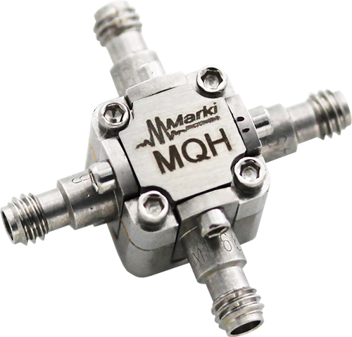
The MQH-40110M2 is a 40–110 GHz quadrature (90°) hybrid in our miniature M2-package enabling operation up to 110 GHz. The quad hybrid features exceptional amplitude and phase balance and high isolation between the quadrature ports. Passive GaAs MMIC technology allows production of smaller constructions that replace larger form factor circuit board constructions. Tight fabrication tolerances allow for less unit-to-unit variation than traditional quadrature hybrid technologies. Low variation allows for accurate simulations using the provided S4P file taken from measured production units. The MQH-40110M2 is available as a 1.0mm connectorized module.

| Part Number | Description | Package | Connectors | Green Status | Product Lifecycle | Export Classification |
|---|---|---|---|---|---|---|
| MQH-40110M2 | MMIC 40-110GHz Quadrature Hybrid | M2 | Standard | REACH RoHS | Released | EAR99 |
| Part Number | Description | Package | Connectors | Green Status | Product Lifecycle | Export Classification |
|---|---|---|---|---|---|---|
| MQH-40110M2 | MMIC 40-110GHz Quadrature Hybrid | M2 | Standard | REACH RoHS | Released | EAR99 |
MQH-40110M2
MMIC 40-110GHz Quadrature Hybrid
MQH-40110M2
MMIC 40-110GHz Quadrature Hybrid
A top-down view of the MQH-40110M2 package outline drawing is shown below. This MMIC quadrature hybrid is a passive reciprocal device allowing any port to be used as the input. Ports 1 – 4 correspond to the M2 package designation.
| Port | Function | Connector Type | Description | DC Equivalent Circuit |
|---|---|---|---|---|
| GND | Ground | - | M2 package ground path is provided through the metal housing. |  |
| Port 1 | Input/Output | 1.0F | Port 1 is DC short to port 2 and open to ground. |  |
| Port 2 | 0° Output/Input | 1.0F | Port 2 is DC short to port 1 and open to ground. | |
| Port 3 | 90° Output/Input | 1.0F | Port 3 is DC short to port 4 and open to ground. | |
| Port 4 | Isolated | 1.0F | Port 4 is DC short to port 3 and open to ground. | |
MQH-40110M2
MMIC 40-110GHz Quadrature Hybrid
| Port | Function | Connector Type | Description | DC Equivalent Circuit |
|---|---|---|---|---|
| GND | Ground | - | M2 package ground path is provided through the metal housing. | |
| Port 1 | 0° Output/Input | 1.0F | Port 1 is DC short to port 2 and open to ground. | |
| Port 2 | Input/Output | 1.0F | Port 2 is DC short to port 1 and open to ground. | |
| Port 3 | Isolated | 1.0F | Port 3 is DC short to port 4 and open to ground. | |
| Port 4 | 90° Output/Input | 1.0F | Port 4 is DC short to port 3 and open to ground. | |
MQH-40110M2
MMIC 40-110GHz Quadrature Hybrid
| Port | Function | Connector Type | Description | DC Equivalent Circuit |
|---|---|---|---|---|
| GND | Ground | - | M2 package ground path is provided through the metal housing. | |
| Port 1 | 90° Output/Input | 1.0F | Port 1 is DC short to port 2 and open to ground. | |
| Port 2 | Isolated | 1.0F | Port 2 is DC short to port 1 and open to ground. | |
| Port 3 | Input/Output | 1.0F | Port 3 is DC short to port 4 and open to ground. | |
| Port 4 | 0° Output/Input | 1.0F | Port 4 is DC short to port 3 and open to ground. | |
MQH-40110M2
MMIC 40-110GHz Quadrature Hybrid
| Port | Function | Connector Type | Description | DC Equivalent Circuit |
|---|---|---|---|---|
| GND | Ground | - | M2 package ground path is provided through the metal housing. | |
| Port 1 | Isolated | 1.0F | Port 1 is DC short to port 2 and open to ground. | |
| Port 2 | 90° Output/Input | 1.0F | Port 2 is DC short to port 1 and open to ground. | |
| Port 3 | 0° Output/Input | 1.0F | Port 3 is DC short to port 4 and open to ground. | |
| Port 4 | Input/Output | 1.0F | Port 4 is DC short to port 3 and open to ground. | |
MQH-40110M2
MMIC 40-110GHz Quadrature Hybrid
The Absolute Maximum Ratings indicate limits beyond which damage may occur to the device. If these limits are exceeded, the device may be inoperable or have a reduced lifetime.
| Parameter | Maximum Rating | Unit |
|---|---|---|
| DC Current, at any Port | 48 | mA |
| Maximum Operating Temperature | 100 | °C |
| Maximum Storage Temperature | 125 | °C |
| Minimum Operating Temperature | -55 | °C |
| Minimum Storage Temperature | -65 | °C |
| Power Handling, at any Port | 1 | W |
| Parameter | Details | Rating |
|---|---|---|
| ESD | 250 to < 500 Volts | HBM Class 1A |
| Dimensions | - | 27.62 x 27.63 mm |
MQH-40110M2
MMIC 40-110GHz Quadrature Hybrid
The electrical specifications apply at TA=+25°C in a 50Ω system. Min and Max limits are guaranteed at TA=+25°C.
| Parameter | Port Configuration | Test Conditions | Minimum Frequency (GHz) | Maximum Frequency (GHz) | Min | Typ | Max | Unit |
|---|---|---|---|---|---|---|---|---|
| Amplitude Balance | - | - | 40 | 110 | - | 1 | 3 | dB |
| Excess Insertion Loss | - | - | 40 | 110 | - | 2.5 | 5 | dB |
| Impedance | - | - | 40 | 110 | - | 50 | - | Ω |
| Isolation | - | - | 40 | 110 | - | 18 | - | dB |
| Mean Coupling | - | - | 40 | 110 | - | 3 | - | dB |
| Nominal Phase Shift | - | - | 40 | 110 | - | 90 | - | ° |
| Phase Balance | - | - | 40 | 110 | - | 5 | 15 | ° |
| Return Loss | - | - | 40 | 110 | - | 13 | - | dB |
MQH-40110M2
MMIC 40-110GHz Quadrature Hybrid


MQH-40110M2
MMIC 40-110GHz Quadrature Hybrid
