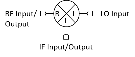
Port Diagram

NOT RECOMMENDED FOR NEW DESIGN
Sales: 408-778-9952 | General: 408-778-4200 | Fax: 408-778-4300
Sales & Customer Support: [email protected]
Tech Support: [email protected]
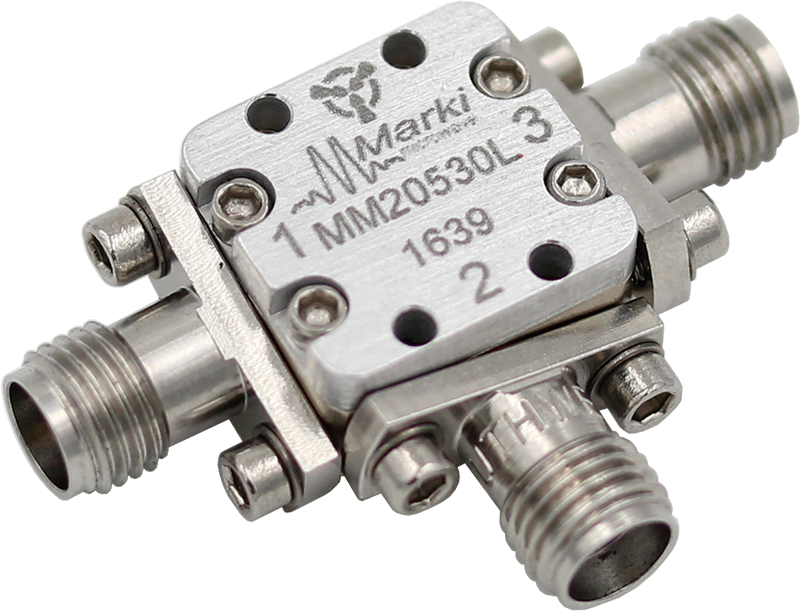
The MM2-0530L is a passive MMIC triple balanced mixer. It features a broadband IF port that spans from 2 to 20 GHz, and has excellent spurious suppression. GaAs MMIC technology improves upon the previous generation of hand assembled, hybrid M2 triple balanced mixers with improved isolations, unit-to-unit repeatability and reliability. The MM2-0530L is available as a wire bondable chip or connectorized SMA package. For new designs, refer to the MM2-0530LBH.
N/A
| Part Number | Description | Package | Connectors | Green Status | Product Lifecycle | Export Classification | Recommended Replacement |
|---|---|---|---|---|---|---|---|
| MM2-0530LS | GaAs MMIC Triple Balanced Mixer | S | Standard | REACH RoHS | Not Recommended for New Design | EAR99 | MM2-0530LBH |
MM2-0530LS
GaAs MMIC Triple Balanced Mixer
| Revision Code | Revision Date | Comment |
|---|---|---|
| - | 2016-01-01 | Initial Release |
| A | 2026-02-13 | MTTF Table Added |
MM2-0530LS
GaAs MMIC Triple Balanced Mixer
| Port | Function | Connector Type | Description | DC Equivalent Circuit |
|---|---|---|---|---|
| Port 1 | LO | 2.92F | Port 1 is DC short and AC matched to 50 Ω from 5 to 30 GHz. Blocking capacitor is optional. |  |
| Port 2 | IF | SMAF | Port 2 is DC coupled to the diodes. Blocking capacitor is optional. |  |
| Port 3 | RF | 2.92F | Port 3 is DC short and AC matched to 50 Ω from 5 to 30 GHz. Blocking capacitor is optional. | |
MM2-0530LS
GaAs MMIC Triple Balanced Mixer
| Port | Function | Connector Type | Description | DC Equivalent Circuit |
|---|---|---|---|---|
| Port 1 | RF | 2.92F | Port 1 is DC short and AC matched to 50 Ω from 5 to 30 GHz. Blocking capacitor is optional. | |
| Port 2 | IF | SMAF | Port 2 is DC coupled to the diodes. Blocking capacitor is optional. | - |
| Port 3 | LO | 2.92F | Port 3 is DC short and AC matched to 50 Ω from 5 to 30 GHz. Blocking capacitor is optional. | |
MM2-0530LS
GaAs MMIC Triple Balanced Mixer
| Parameter | Maximum Rating | Unit |
|---|---|---|
| Maximum Operating Temperature | 100 | °C |
| Maximum Storage Temperature | 125 | °C |
| Minimum Operating Temperature | -55 | °C |
| Minimum Storage Temperature | -65 | °C |
| Port 1 DC Current | 21 | mA |
| Port 2 DC Current | 15 | mA |
| Port 3 DC Current | 24 | mA |
| RF Power Handling (RF+LO), 100°C | 20 | dBm |
| RF Power Handling (RF+LO), 25°C | 25 | dBm |
| T (°C) | λ (TIF) | MTTF (hr) | MTTF (yr) |
|---|---|---|---|
| 125 | 6,494.37 | 153,980 | 17.57757 |
| 85 | 644.3396 | 1,551,977 | 177.1663 |
| 55 | 78.70691 | 1.3E+07 | 1,450.384 |
| 40 | 23.6513 | 4.2E+07 | 4,826.595 |
| 25 | 6.297343 | 1.6E+08 | 18,127.53 |
| Parameter | Details | Rating |
|---|---|---|
| ESD | 250 to < 500 Volts | HBM Class 1A |
| Dimensions | - | 14.22 x 13.21mm |
| Parameter | Min | Nominal | Max | Unit |
|---|---|---|---|---|
| LO Input Power | 9 | - | 17 | - |
MM2-0530LS
GaAs MMIC Triple Balanced Mixer
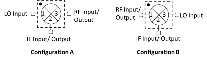
Specifications guaranteed from -55 to +100°C, measured in a 50Ω system. Specifications are shown for Configurations A (B). RF testing is performed on a sample basis to verify conformance to datasheet guaranteed specifications. Consult factory for more information.
| Parameter | Port Configuration | Test Conditions | Min | Typ | Max | Unit |
|---|---|---|---|---|---|---|
| Conversion Loss 1 | A | LO/RF=5-30 GHz IF=2-20 GHz LO Drive Level=15 | - | 9 | - | dB |
| Input IP3 2 | A | LO/RF=5-30 GHz IF=2-20 GHz LO Drive Level= 9-17 | - | 15 | - | dBm |
| Input P1dB | A | LO/RF=5-30 GHz IF=2-20 GHz LO Drive Level= 9-17 | - | 8 | - | dBm |
| LO-RF Isolation | A | - | - | 44 | - | dB |
| Conversion Loss 3 | B | LO/RF=5-30 GHz IF=2-20 GHz LO Drive Level=15 | - | 10 | - | dB |
| Input IP3 4 | B | LO/RF=5-30 GHz IF=2-20 GHz LO Drive Level= 9-17 | - | 19 | - | dBm |
| Input P1dB | B | LO/RF=5-30 GHz IF=2-20 GHz LO Drive Level= 9-17 | - | 10 | - | dBm |
| IF Frequency Range | - | - | 2 | - | 20 | GHz |
| LO Frequency Range | - | - | 5 | - | 30 | GHz |
| RF Frequency Range | - | - | 5 | - | 30 | GHz |
[1][3] Measured Conversion Loss measured at 3 GHz fixed IF
[2][4] IP3 depends on LO drive conditions, see plots for more details
MM2-0530LS
GaAs MMIC Triple Balanced Mixer


MM2-0530LS
GaAs MMIC Triple Balanced Mixer


MM2-0530LS
GaAs MMIC Triple Balanced Mixer


MM2-0530LS
GaAs MMIC Triple Balanced Mixer


MM2-0530LS
GaAs MMIC Triple Balanced Mixer
MM2-0530LS
GaAs MMIC Triple Balanced Mixer
