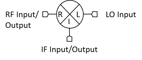
Port Diagram
Sales: 408-778-9952 | General: 408-778-4200 | Fax: 408-778-4300
Sales & Customer Support: [email protected]
Tech Support: [email protected]
M4 diplexed IF mixers are hybrid assemblies that combine a low frequency IF (to DC) with a multi-decade bandwidth RF and LO. M4 mixers are commonly used for single tone analyzers (such as antenna test systems) with ultra-broad frequency ranges.
N/A
| Part Number | Description | Package | Connectors | Green Status | Product Lifecycle | Export Classification |
|---|---|---|---|---|---|---|
| M4-0140LK | Double-Balanced 1 - 40 GHz Mixers | K | Standard | Consult Factory | Released | EAR99 |
| M4-0140HK | Double-Balanced 1 - 40 GHz Mixers | K | Standard | Consult Factory | End of Life | EAR99 |
| M4-0140LKV | Double-Balanced 1 - 40 GHz Mixers | - | Standard | Consult Factory | Released | EAR99 |
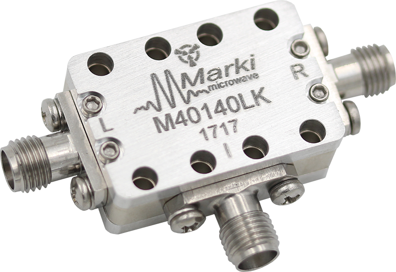
M4-0140LK
Double-Balanced 1 - 40 GHz Mixers
| Revision Code | Revision Date | Comment |
|---|---|---|
| - | 2023-09-01 | Initial Release on New Format |
| A | 2024-03-20 | Updated Performance Plots due to Diode Change |
M4-0140LK
Double-Balanced 1 - 40 GHz Mixers
| Port | Function | Connector Type | Description | DC Equivalent Circuit |
|---|---|---|---|---|
| Port 1 | LO | 2.92F | Port 1 is DC short for the K package. |  |
| Port 2 | IF | 2.92F | Port 2 is diode connected for the K Package. |  |
| Port 3 | RF | SMAF | Port 3 is DC short for the K Package. | |
M4-0140LK
Double-Balanced 1 - 40 GHz Mixers
| Parameter | Details | Rating |
|---|---|---|
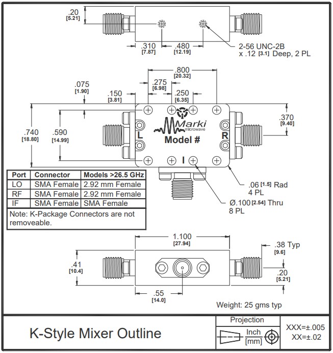
| Weight | Package name: K | 25g |
| Dimensions | - | 20.32 x 18.80 mm |
| Parameter | Min | Nominal | Max | Unit |
|---|---|---|---|---|
| LO Input Power | 10 | - | 13 | - |
M4-0140LK
Double-Balanced 1 - 40 GHz Mixers
Specifications guaranteed from -55 to +100°C, measured in a 50-Ohm system.
| Parameter | Test Conditions | Min | Typ | Max | Unit |
|---|---|---|---|---|---|
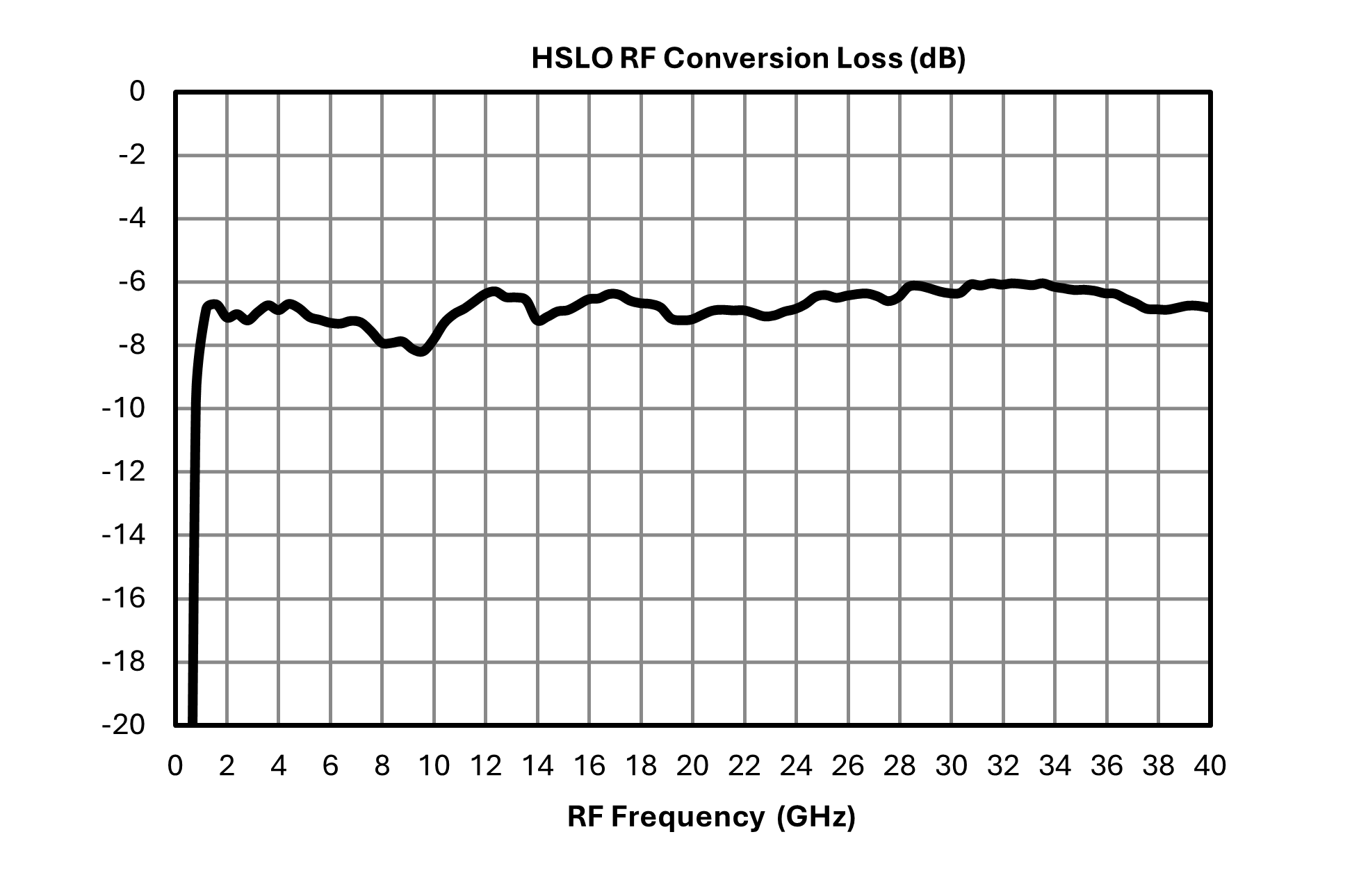
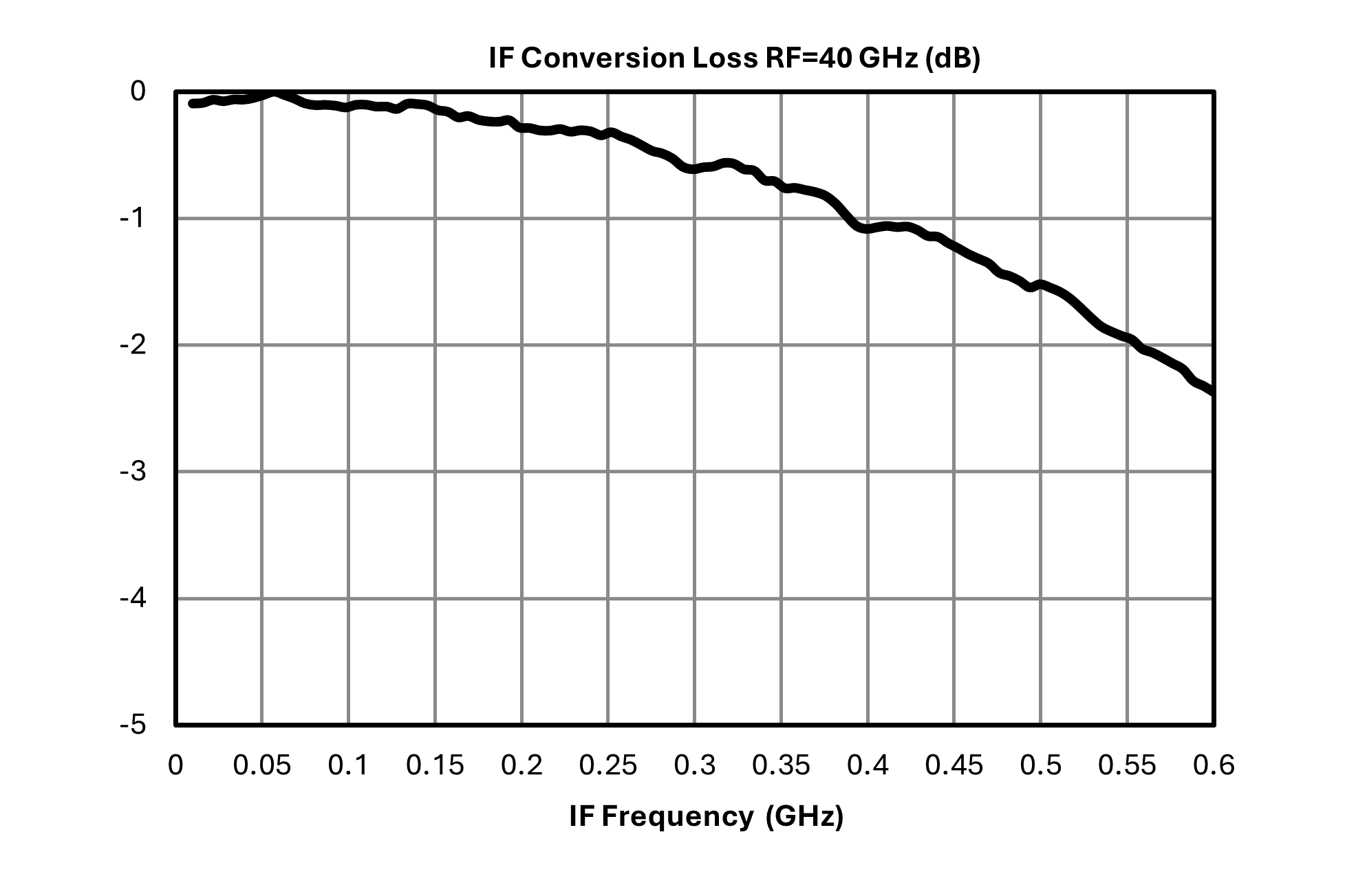
| Conversion Loss | LO/RF=1-40 GHz IF=DC-0.5 GHz | - | 9.5 | 12 | dB |
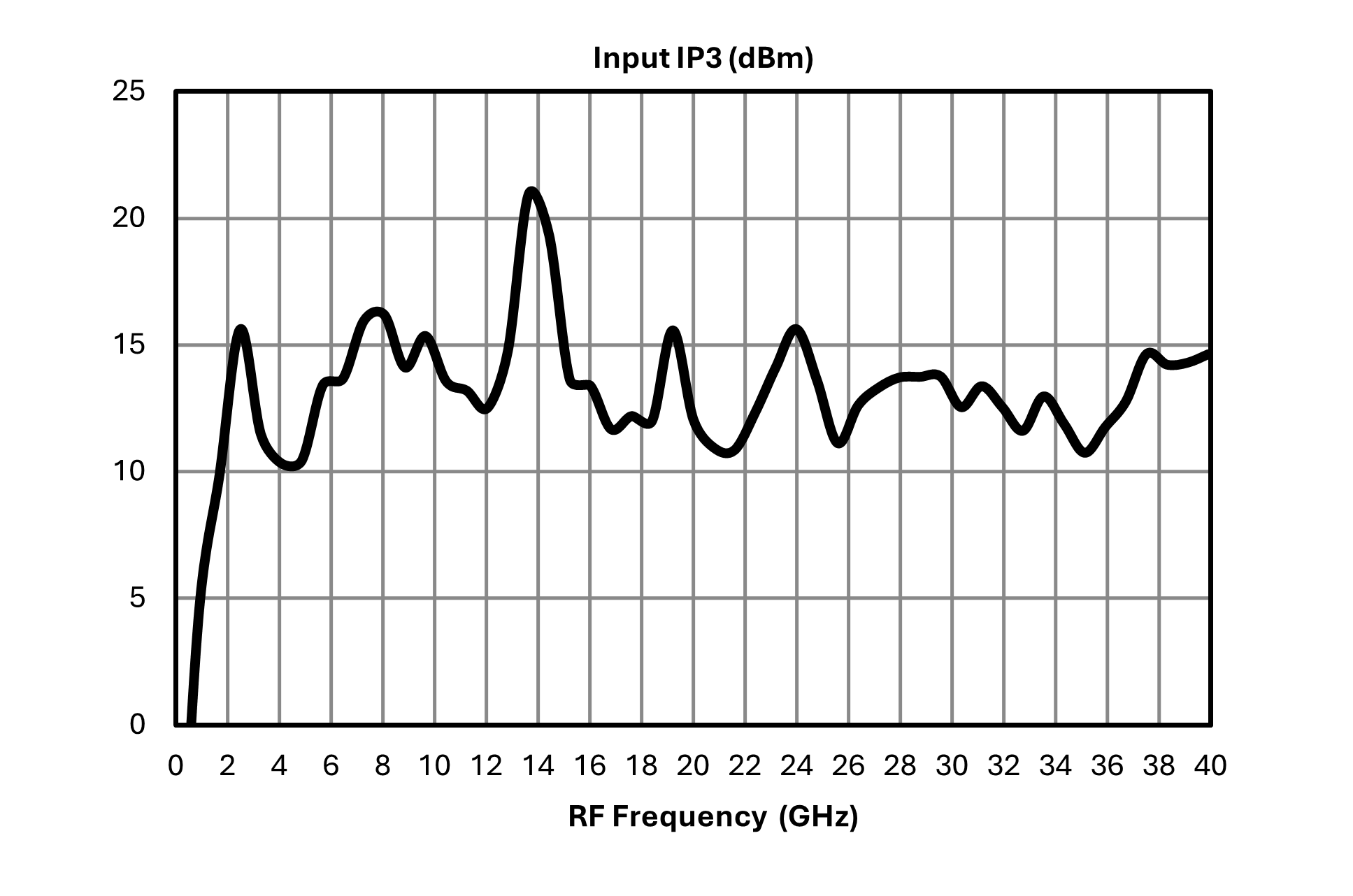
| Input IP3 | LO/RF=1-40 GHz L diode level 10-13 dBm | - | 13 | - | dBm |
| Input P1dB | LO/RF=1-40 GHz L diode level 10-13 dBm | - | 3 | - | dBm |
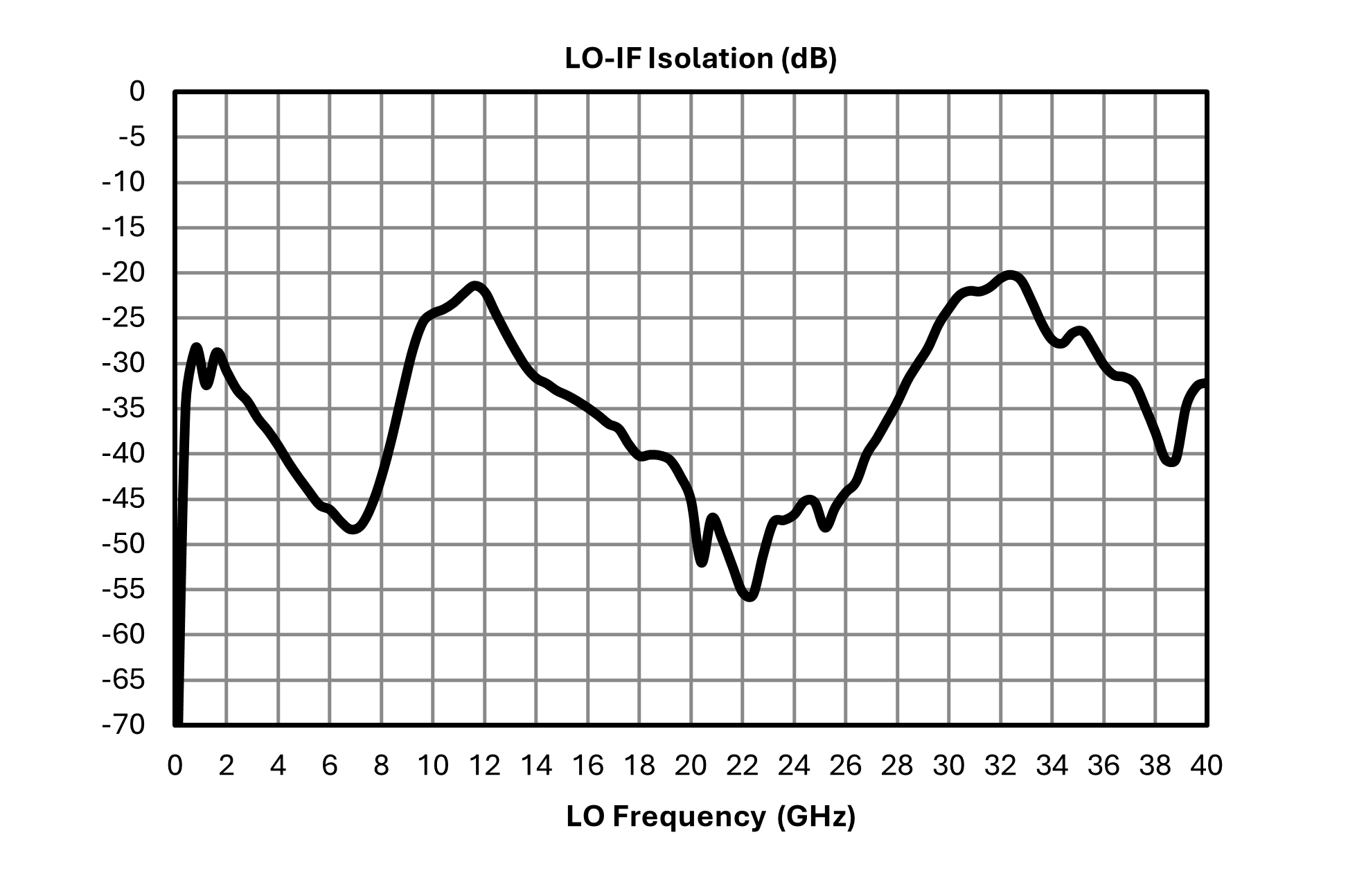
| LO-IF Isolation | LO/RF=1-40 GHz | - | 27 | - | dB |
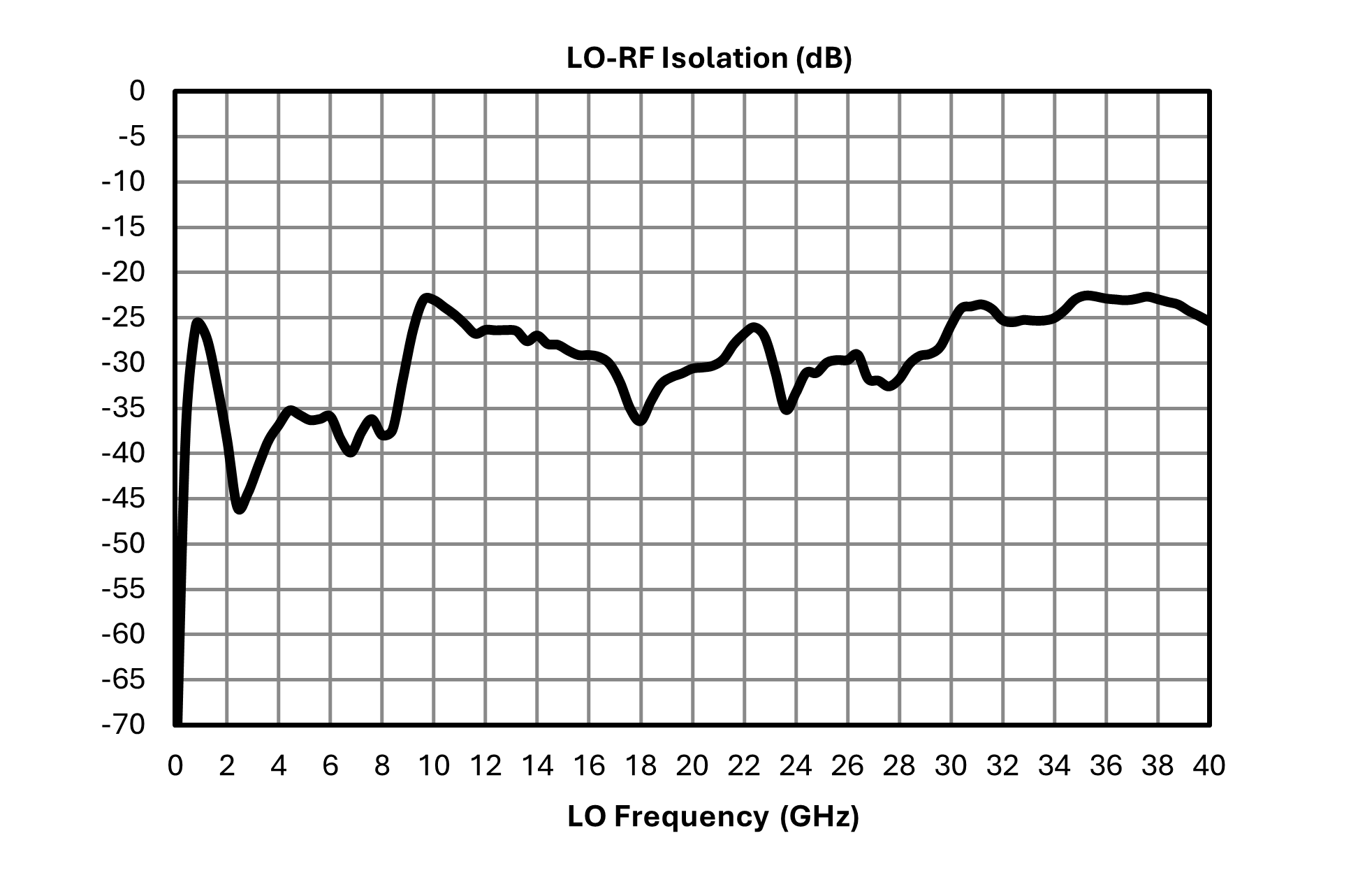
| LO-RF Isolation | LO/RF=1-40 GHz | 20 | 30 | - | dB |
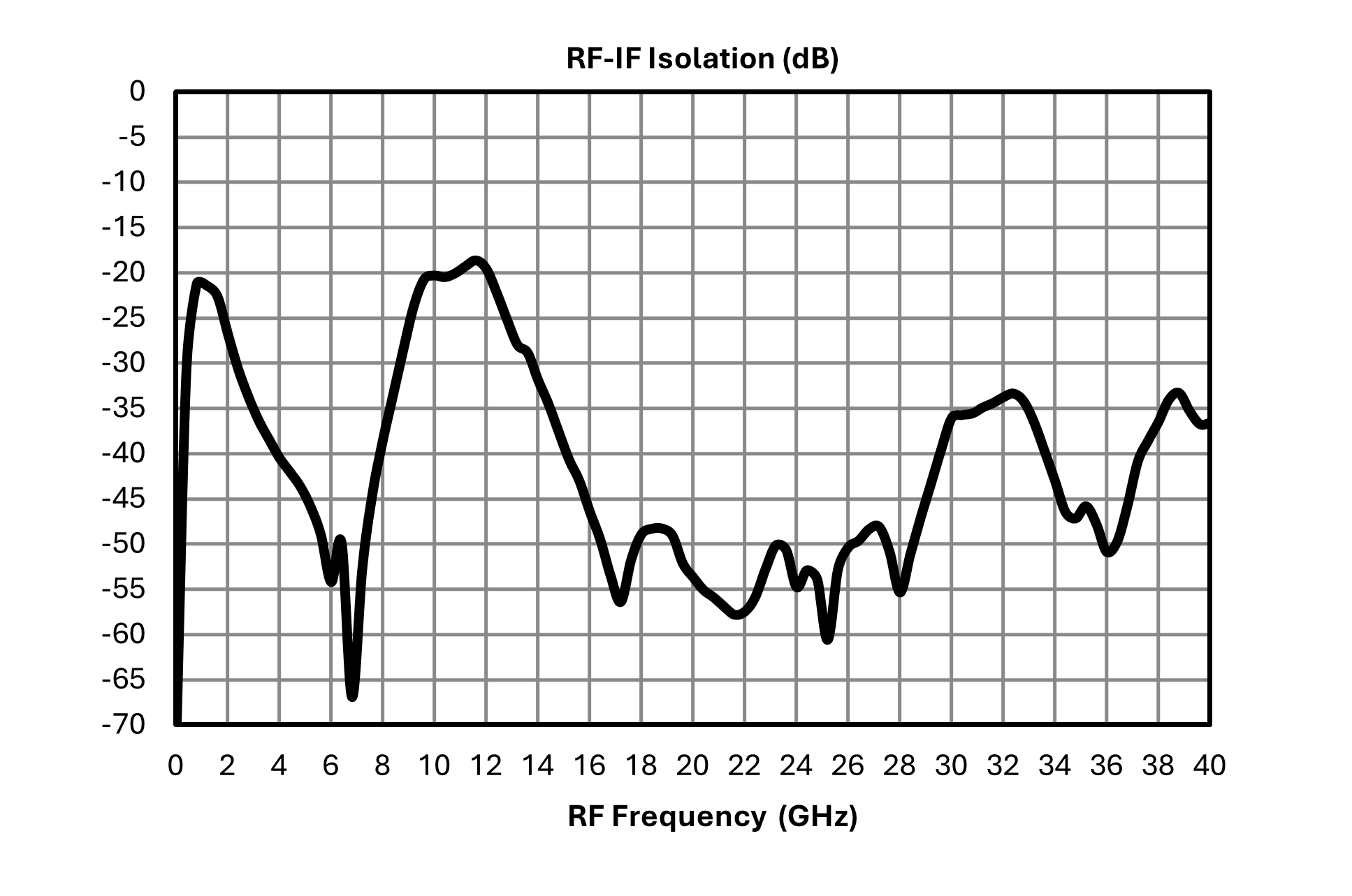
| RF-IF Isolation | LO/RF=1-40 GHz | - | 25 | - | dB |
| IF Frequency Range | - | 0 | - | 0.5 | GHz |
| RF Frequency Range | - | 1 | - | 40 | GHz |
| Parameter | Test Conditions | Min | Typ | Max | Unit |
|---|---|---|---|---|---|
| Conversion Loss | LO/RF=1-40 GHz IF=DC-0.5 GHz | - | 9.5 | 12 | dB |
| Input IP3 | LO/RF=1-40 GHz L diode level 10-13 dBm | - | 13 | - | dBm |
| Input P1dB | LO/RF=1-40 GHz L diode level 10-13 dBm | - | 3 | - | dBm |
| LO-IF Isolation | LO/RF=1-40 GHz | - | 27 | - | dB |
| LO-RF Isolation | LO/RF=1-40 GHz | 20 | 30 | - | dB |
| RF-IF Isolation | LO/RF=1-40 GHz | - | 25 | - | dB |
| IF Frequency Range | - | 0 | - | 0.5 | GHz |
| RF Frequency Range | - | 1 | - | 40 | GHz |
M4-0140LK
Double-Balanced 1 - 40 GHz Mixers
M4-0140LK
Double-Balanced 1 - 40 GHz Mixers
