Package Information
| Parameter | Details | Rating |
|---|---|---|
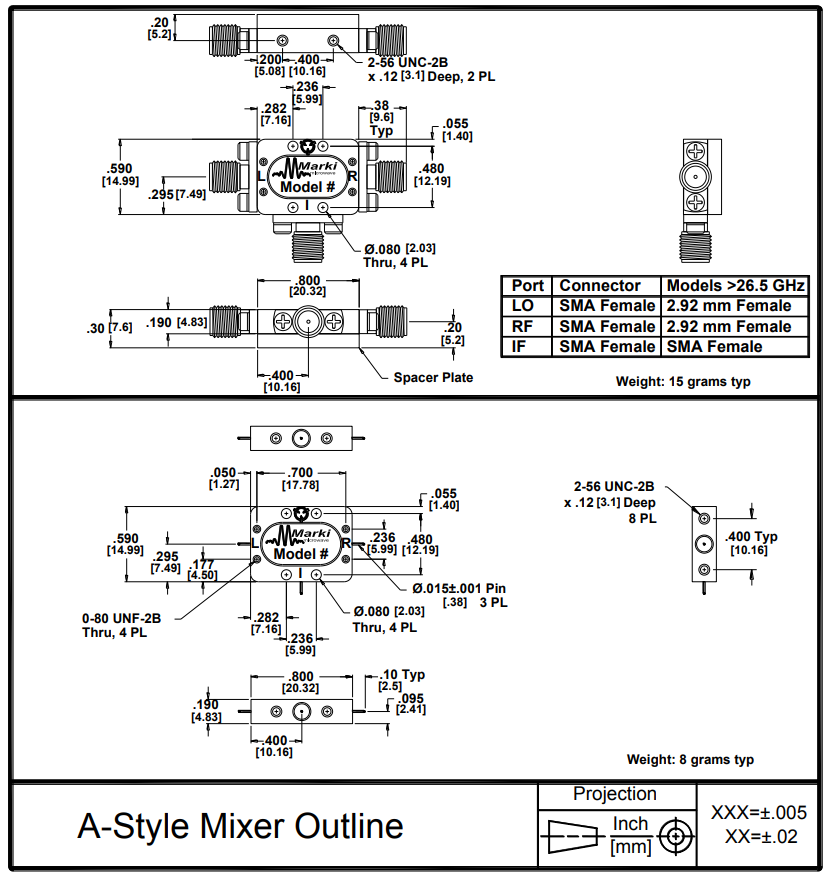
| Dimensions | - | 20.32 x 14.99 mm |
NOT RECOMMENDED FOR NEW DESIGN
Sales: 408-778-9952 | General: 408-778-4200 | Fax: 408-778-4300
Sales & Customer Support: [email protected]
Tech Support: [email protected]
M1 double balanced mixers are hybrid assemblies that have been hand-tuned to feature low conversion loss and high isolations and a DC IF response. M1 mixers have generally been replaced with MM1 mixers with superior performance, repeatability, and availability. M1 mixers are still used in legacy systems and are suitable for laboratory use.
N/A
| Part Number | Description | Package | Connectors | Green Status | Product Lifecycle | Export Classification | Recommended Replacement |
|---|---|---|---|---|---|---|---|
| M1-0616MP | Double-Balanced Mixers | P | Standard | Consult Factory | Not Recommended for New Design | EAR99 | MM1-0320HSMM1-0320LS |
| M1-0616MA | Double-Balanced Mixer | A | Standard | Consult Factory | Not Recommended for New Design | EAR99 | - |
| M1-0616NP | Double-Balanced Mixers | P | Standard | Consult Factory | End of Life | EAR99 | MM1-0320HS |
| M1-0616HP | Double-Balanced Mixers | P | Standard | Consult Factory | End of Life | EAR99 | MM1-0320HS |
| M1-0616LP | Double-Balanced Mixers | P | Standard | Non-RoHS | End of Life | EAR99 | MM1-0320LS |
M1-0616MA
Double-Balanced Mixer
| Revision Code | Revision Date | Comment |
|---|---|---|
| - | 2015-01-01 | Initial Datasheet Release |
| A | 2024-03-07 | Revised electrical specs table for Conversion Loss and LO-to-RF Isolation specifications. |
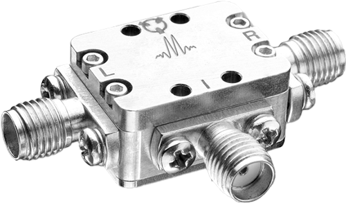
M1-0616MA
Double-Balanced Mixer
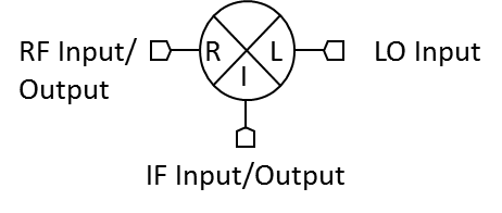
| Port | Function | Connector Type | Description | DC Equivalent Circuit |
|---|---|---|---|---|
| Port 1 | LO | SMAF | Port 1 is DC short for the P package. |  |
| Port 2 | IF | SMAF | Port 2 is diode connected for the P Package. |  |
| Port 3 | RF | SMAF | Port 3 is DC short for the P Package. | |
M1-0616MA
Double-Balanced Mixer
| Parameter | Details | Rating |
|---|---|---|
| Dimensions | - | 20.32 x 14.99 mm |
| Parameter | Min | Nominal | Max | Unit |
|---|---|---|---|---|
| LO Input Power | 10 | - | 13 | - |
M1-0616MA
Double-Balanced Mixer
Specifications guaranteed from -55 to +100°C, measured in a 50-Ohm system.
| Parameter | Test Conditions | Min | Typ | Max | Unit |
|---|---|---|---|---|---|
| Conversion Loss | LO/RF=6-16 GHz IF=2-4 GHz | - | 6.5 | 10.5 | dB |
| Conversion Loss | LO/RF=6-16 GHz IF=DC-2 GHz | - | 5.5 | 8 | dB |
| IF Frequency Range | - | 0 | - | 4 | GHz |
| Input IP3 | LO/RF=6-16 GHz LO drive level, M Diode Option=10-13 dBm | - | 15 | - | dBm |
| Input IP3 | - | - | 15 | - | dBm |
| Input P1dB | LO/RF=6-16 GHz LO drive level, M Diode Option=10-13 dBm | - | 5 | - | dBm |
| Input P1dB | - | - | 5 | - | dBm |
| LO-IF Isolation | LO/RF=6-16 GHz | - | 30 | - | dB |
| LO-RF Isolation | LO/RF=6-16 GHz | 20 | 35 | - | dB |
| RF Frequency Range | - | 6 | - | 16 | GHz |
| RF-IF Isolation | LO/RF=6-16 GHz | - | 25 | - | dB |
M1-0616MA
Double-Balanced Mixer