- LO/RF 2.0 to 4.0 GHz
- IF DC to 2.0 GHz
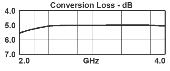
- 5.0 dB Typical Conversion Loss
- 35 dB Typical LO to RF Isolation
END OF LIFE
Sales: 408-778-9952 | General: 408-778-4200 | Fax: 408-778-4300
Sales & Customer Support: [email protected]
Tech Support: [email protected]
Device Overview
General Description
M1 double balanced mixers are hybrid assemblies that have been hand-tuned to feature low conversion loss and high isolations and a DC IF response. M1 mixers have generally been replaced with MM1 mixers with superior performance, repeatability, and availability. M1 mixers are still used in legacy systems and are suitable for laboratory use.
Features
Applications
N/A
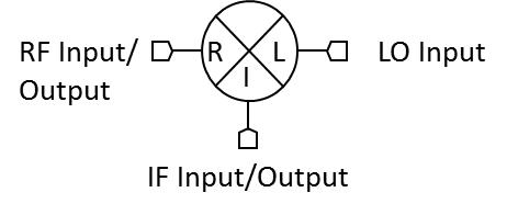
Functional Block Diagram
Part Ordering Options
| Part Number | Description | Package | Connectors | Green Status | Product Lifecycle | Export Classification | Recommended Replacement |
|---|---|---|---|---|---|---|---|
| M1-0204LP | Double-Balanced Mixers | P | Standard | Consult Factory | Not Recommended for New Design | EAR99 | MM1-0212LS |
| M1-0204MP | Double-Balanced Mixers | P | Standard | Consult Factory | Not Recommended for New Design | EAR99 | MM1-0212LS |
| M1-0204HP | Double-Balanced Mixers | P | Standard | Consult Factory | End of Life | EAR99 | MM1-0212HSMM1-0212SS |
| M1-0204NP | Double-Balanced Mixers | P | Standard | Consult Factory | End of Life | EAR99 | MM1-0212LSMM1-0212HS |
M1-0204HP
Double-Balanced Mixers
Table Of Contents
M1-0204HP
Double-Balanced Mixers
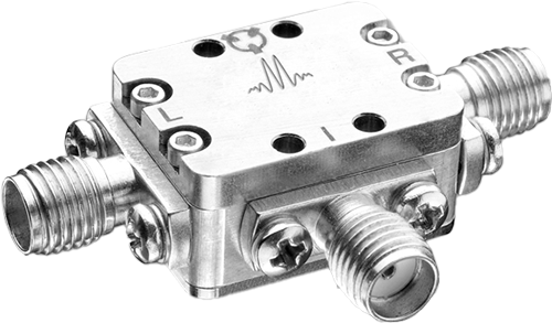
Port Configuration and Functions
Port Functions
| Port | Function | Connector Type | Description | DC Equivalent Circuit |
|---|---|---|---|---|
| Port 1 | LO | SMAF | Port 1 is DC short for the P package. |  |
| Port 2 | IF | SMAF | Port 2 is diode connected for the P Package. |  |
| Port 3 | RF | SMAF | Port 3 is DC short for the P Package. | |
M1-0204HP
Double-Balanced Mixers
Specifications
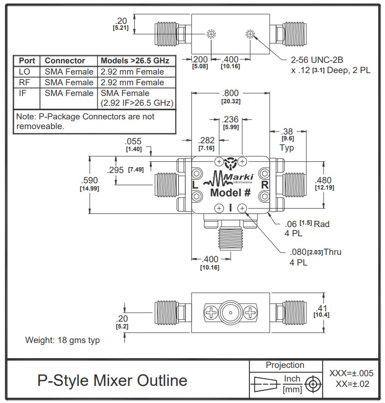
Package Information
| Parameter | Details | Rating |
|---|---|---|
| Weight | Package name: P | 18g |
| Dimensions | - | 20.32 x 14.99 mm |
Recommended Operating Conditions
| Parameter | Min | Nominal | Max | Unit |
|---|---|---|---|---|
| LO Input Power | 16 | - | 19 | - |
M1-0204HP
Double-Balanced Mixers
Electrical Specifications
| Parameter | Test Conditions | Min | Typ | Max | Unit |
|---|---|---|---|---|---|
| Conversion Loss | LO/RF=2-4 GHz IF=1-2 GHz | - | 6 | 8 | dB |
| Conversion Loss | LO/RF=2-4 GHz IF=DC-1 GHz | - | 5 | 7 | dB |
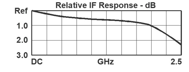
| IF Frequency Range | - | 0 | - | 2 | GHz |
| Input IP3 | LO/RF=2-4 GHz LO drive level, H Diode Option=16-19 dBm | - | 21 | - | dBm |
| Input P1dB | LO/RF=2-4 GHz LO drive level, H Diode Option=16-19 dBm | - | 11 | - | dBm |
| LO Drive Level | - | 16 | - | 19 | dBm |
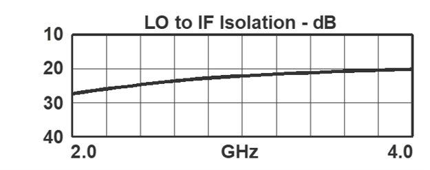
| LO-IF Isolation | LO/RF=2-4 GHz | - | 20 | - | dB |
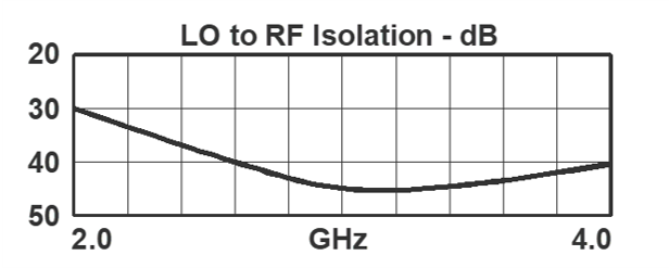
| LO-RF Isolation | LO/RF=2-4 GHz | 25 | 38 | - | dB |
| RF Frequency Range | - | 2 | - | 4 | GHz |
| RF-IF Isolation | LO/RF=2-4 GHz | - | 25 | - | dB |
| Input IP3 | - | - | 21 | - | dBm |
| Input P1dB | - | - | 11 | - | dBm |
| Parameter | Test Conditions | Min | Typ | Max | Unit |
|---|---|---|---|---|---|
| Conversion Loss | LO/RF=2-4 GHz IF=1-2 GHz | - | 6 | 8 | dB |
| Conversion Loss | LO/RF=2-4 GHz IF=DC-1 GHz | - | 5 | 7 | dB |
| IF Frequency Range | - | 0 | - | 2 | GHz |
| Input IP3 | LO/RF=2-4 GHz LO drive level, H Diode Option=16-19 dBm | - | 21 | - | dBm |
| Input P1dB | LO/RF=2-4 GHz LO drive level, H Diode Option=16-19 dBm | - | 11 | - | dBm |
| LO Drive Level | - | 16 | - | 19 | dBm |
| LO-IF Isolation | LO/RF=2-4 GHz | - | 20 | - | dB |
| LO-RF Isolation | LO/RF=2-4 GHz | 25 | 38 | - | dB |
| RF Frequency Range | - | 2 | - | 4 | GHz |
| RF-IF Isolation | LO/RF=2-4 GHz | - | 25 | - | dB |
| Input IP3 | - | - | 21 | - | dBm |
| Input P1dB | - | - | 11 | - | dBm |
M1-0204HP
Double-Balanced Mixers
Typical Performance
M1-0204HP
Double-Balanced Mixers