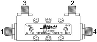
Device Overview

General Description

The CE13-0240 is a next generation broadband 2GHz to 40GHz, 13dB directional coupler from the Marki Elite Series. Conductive paint is applied to all Elite Series products to reduce EMI/RFI leakage and susceptibility. The CE13-0240 offers the best directivity, return loss, and coupling accuracy available on the market. Available as both a three port directional coupler and a four port bidirectional coupler, the CE13-0240 is an exceptional choice for broadband return loss measurements, power leveling, and signal monitoring applications. Sophisticated neural network design techniques combined with deep circuit knowledge and triplate stripline construction allow the Marki Elite Series of Couplers to provide superior performance to all other directional couplers available.

Photo of CE13-0240

Features

  • Broadband Performance
  • Excellent Coupling Flatness
  • High Directivity
  • Low VSWR
  • Conductive paint minimizes RF leakage

Applications

N/A

Functional Block Diagram

Block Diagram

Part Ordering Options

Part NumberDescriptionConnectorsGreen StatusProduct LifecycleExport Classification
CE13-0240T Elite 2-40 GHz Directional CouplerStandard

REACH

RoHS

ReleasedEAR99
CE13-0240Elite 2-40 GHz Directional CouplerStandard

REACH

RoHS

ReleasedEAR99

Table Of Contents

Revision History

Revision CodeRevision DateComment
-2021-12-01Datasheet Initial Release
A2022-04-01Terminated Option Added, Operating and Storage Temperatures Updated

Rev: A | Copyright © 2021 - 2022 Marki Microwave LLC.

2

Port Configuration and Functions

Port Diagram

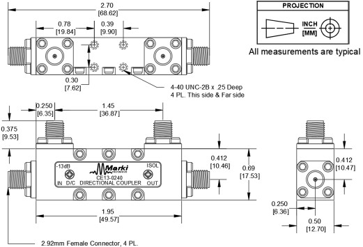
A side view of the CE13-0240 package outline drawing is shown below. The CE13-0240 has input and output ports given in Port Functions. The CE13-0240 can be used in either the forward or reverse direction corresponding to configuration A and B respectively. For configuration A, input signal into port 1, use port 3 for coupled port, port 2 for isolated port, and port 4 for output port. For configuration B, input signal into port 4, use port 2 for coupled port, port 3 for isolated port, and port 1 for output port.

Diagram of the port configuration for CE13-0240

Port Functions

Configuration A

PortFunctionConnector TypeDescriptionDC Equivalent
Circuit
Port 1Input 2.92FThe input port is DC short to the output port and open to the isolated and coupled ports.Equivalent circuit for the Input
Port 2Isolated 2.92FThe isolated port is DC short to the coupled port and open to the input and output ports.Equivalent circuit for the Isolated
Port 3Coupled 2.92FThe coupled port is DC short to the isolated port and open to the input and output ports.Equivalent circuit for the Coupled
Port 4Output 2.92FThe output port is DC short to the input port and open to the isolated and coupled ports.Equivalent circuit for the Output

Rev: A | Copyright © 2021 - 2022 Marki Microwave LLC.

3

Configuration B

PortFunctionConnector TypeDescriptionDC Equivalent
Circuit
Port 1Output 2.92FThe input port is DC short to the output port and open to the isolated and coupled ports.Equivalent circuit for the Output
Port 2Coupled 2.92FThe isolated port is DC short to the coupled port and open to the input and output ports.Equivalent circuit for the Coupled
Port 3Isolated 2.92FThe coupled port is DC short to the isolated port and open to the input and output ports.Equivalent circuit for the Isolated
Port 4Input 2.92FThe output port is DC short to the input port and open to the isolated and coupled ports.Equivalent circuit for the Input

Rev: A | Copyright © 2021 - 2022 Marki Microwave LLC.

4

Specifications

Absolute Maximum Ratings

The Absolute Maximum Ratings indicate limits beyond which damage may occur to the device. If these limits are exceeded, the device may be inoperable or have a reduced lifetime. Min and Max limits are guaranteed at TA=+25°C.

ParameterMaximum RatingUnit
RF Power Handling 20W
Minimum Operating Temperature -55°C
Maximum Operating Temperature 100°C
Minimum Storage Temperature -65°C
Maximum Storage Temperature 125°C

Package Information

ParameterDetailsRating
Dimensions-49.57 × 17.53 mm

Rev: A | Copyright © 2021 - 2022 Marki Microwave LLC.

5

Electrical Specifications

The electrical specifications apply at TA=+25°C in a 50Ω system

ParameterPort ConfigurationTest ConditionsMinimum
Frequency
(GHz)
Maximum
Frequency
(GHz)
MinTypMaxUnit
Amplitude Flatness 1--2 40-0.150.4dB
Coupling Loss 2--2 400.20.220.25dB
Directivity --2 401728-dB
Direct Line Insertion Loss -DC-40
- --0.751.45dB
Excess Insertion Loss (dB) 3-DC-40
- --0.51.2dB
IL Corrected Directivity 4--2 401729-dB
Impedance --- --50-Ω
Maximum Coupling Deviation --2 40-0.51dB
Mean Coupling --2 4012.51313.5dB
Return Loss -DC-40
- -2030-dB
VSWR -DC-40
- --1.071.22

[1] Amplitude Flatness = Median value of ABS(Measured Coupling Power – Average Coupling Factor).

[2] Coupling loss based on average coupling factor.

[3] Excess Insertion Loss = (Input Port to Output Port Insertion Loss) – Coupling Loss.

[4] IL Corrected Directivity = Directivity + Insertion Loss.

Rev: A | Copyright © 2021 - 2022 Marki Microwave LLC.

6

Typical Performance Plots

Insertion Loss, Return Loss, Coupled Port Power, and Directivity

Insertion Loss (dB) graph for CE13-0240
Return Loss (dB) graph for CE13-0240
Coupling Ratio (dB) graph for CE13-0240
Directivity (dB) graph for CE13-0240
Low Frequency Coupling Ratio (dB) graph for CE13-0240

Rev: A | Copyright © 2021 - 2022 Marki Microwave LLC.

7

Performance Over Temperature

Insertion Loss (dB) graph for CE13-0240
Return Loss (dB) graph for CE13-0240
Coupling Ratio (dB) graph for CE13-0240
Directivity (dB) graph for CE13-0240

Rev: A | Copyright © 2021 - 2022 Marki Microwave LLC.

8

Terminated Return Loss and Directivity

Return Loss (dB) graph for CE13-0240
Directivity (dB) graph for CE13-0240

Rev: A | Copyright © 2021 - 2022 Marki Microwave LLC.

9

Mechanical Data

Rev: A | Copyright © 2021 - 2022 Marki Microwave LLC.

10