Absolute Maximum Ratings
| Parameter | Maximum Rating | Unit |
|---|---|---|
| DC Current | 0.5 | A |
| DC Voltage | 30 | V |
| Maximum Storage Temperature | 125 | °C |
| Minimum Storage Temperature | -65 | °C |
| RF Power Handling | 1 | W |
Sales: 408-778-9952 | General: 408-778-4200 | Fax: 408-778-4300
Sales & Customer Support: [email protected]
Tech Support: [email protected]
The BT-0065 is constructed using a custom-made, resonance-free conical inductor to achieve extremely broadband performance. By minimizing the overall inductor size and using proprietary packaging techniques, the BT-0065 is a superior option in terms of performance, reliability and ease-of-use when compared to cumbersome self-made bias tees employing off-the-shelf conical inductors. The extremely low cutoff and resonance free operation makes the BT-0065 suitable for biasing amplifiers, lasers, and modulators driven with high frequency data patterns.
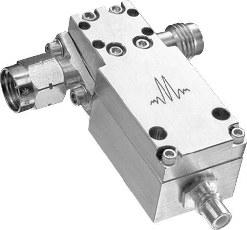

BT-0065
Bias Tee
| Revision Code | Revision Date | Comment |
|---|---|---|
| - | 2010-10-01 | Datasheet Initial Release |
| A | 2019-02-01 | Corrected Low Frequency plots |
| B | 2020-04-01 | Performance vs Bias current plots |
| C | 2020-06-01 | Updated Outline Drawing |
BT-0065
Bias Tee
| Port | Function | Connector Type | Description | DC Equivalent Circuit |
|---|---|---|---|---|
| Common | RF+DC | 1.85M | This port is DC blocked to the RF port and DC connected to the DC port through an internal RF choke. |  |
| DC | DC | - | This port is internally connected to an RF choke which is DC connected to the RF+DC port and DC blocked to the RF port. | |
| RF | RF | 1.85F | This port is internally DC blocked to the RF+DC and DC ports. | |
BT-0065
Bias Tee
| Parameter | Maximum Rating | Unit |
|---|---|---|
| DC Current | 0.5 | A |
| DC Voltage | 30 | V |
| Maximum Storage Temperature | 125 | °C |
| Minimum Storage Temperature | -65 | °C |
| RF Power Handling | 1 | W |
| Parameter | Details | Rating |
|---|---|---|
| Weight | - | 23.5g |
| Dimensions | - | 15.24 x 36.07 mm |
BT-0065
Bias Tee
Specifications guaranteed at +25C, measured in a 50-Ohm system
| Parameter | Test Conditions | Minimum Frequency (GHz) | Maximum Frequency (GHz) | Min | Typ | Max | Unit |
|---|---|---|---|---|---|---|---|
| Capacitance | - | 0.000004 | 65 | - | 1.1 | - | μF |
| DC Port Isolation | - | 0.000004 | 65 | - | 30 | - | dB |
| DC Resistance | - | 0.000004 | 65 | - | 3 | - | Ω |
| Inductance | - | 0.000004 | 65 | - | 1000 | - | μH |
| Insertion Loss | - | 0.000004 | 65 | - | 1.8 | 3 | dB |
| Return Loss | - | 0.000004 | 65 | - | 12 | - | dB |
| Risetime/Falltime 1 | - | 0.000004 | 65 | - | 10 | - | ps |
[1] Specified as 90%/10%. Calculated from 𝜏bt2 = (𝜏out2 - 𝜏in2)
BT-0065
Bias Tee


BT-0065
Bias Tee


BT-0065
Bias Tee
Oscilloscope measurements of the BT-0065 with a 10Gb/s PRBS pattern. Eye diagrams are taken with a 231-1 PRBS input demonstrating minimal eye distortion/closure afforded by the extremely low frequency operation of the bias tee.

BT-0065
Bias Tee
