Package Information
| Parameter | Details | Rating |
|---|---|---|
| Dimensions | - | WR-28 |
Sales: 408-778-9952 | General: 408-778-4200 | Fax: 408-778-4300
Sales & Customer Support: [email protected]
Tech Support: [email protected]
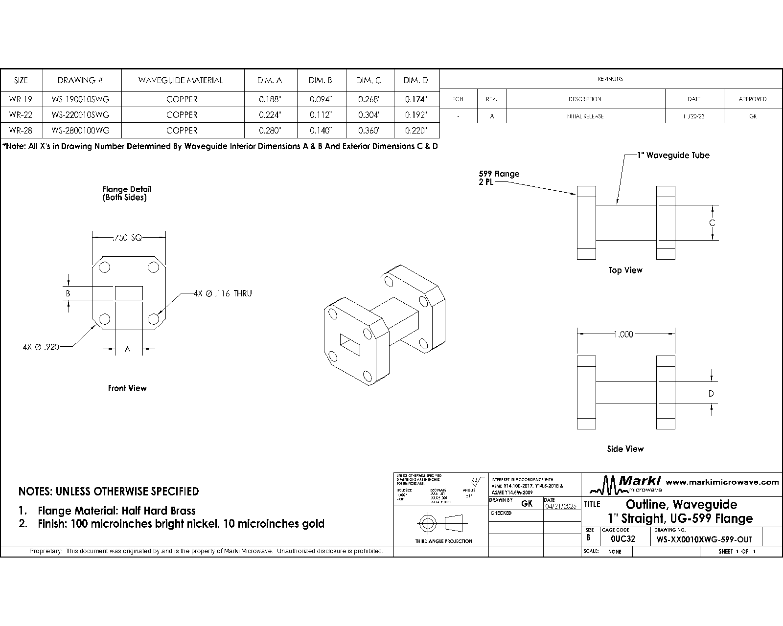
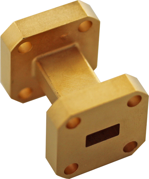
WR-28 Straight Waveguide 1"", Square Flange. Custom lengths available upon request.Marki Microwave straight waveguides are built with high precision and then gold plated for high corrosion resistance. They have very low loss and excellent VSWR. Manufactured to rigid specifications, these transmission line components provide minimum detrimental effects on overall system VSWR.

| Part Number | Description | Package | Green Status | Product Lifecycle | Export Classification |
|---|---|---|---|---|---|
| WS-2800600WG | WR-28 Straight Waveguide 6"". Custom lengths available upon request. | WR-28 | REACH RoHS | Released | EAR99 |
| WS-2800300WG | WR-28 Straight Waveguide 3"". Custom lengths available upon request. | WR-28 | REACH RoHS | Released | EAR99 |
| WS-2800100WG | WR-28 Straight Waveguide, 26.5GHz to 40GHz, 1 in | WR-28 | REACH RoHS | Released | EAR99 |
| WS-2800200WGS | WR-28 Straight Waveguide 2 in. | WR-28 | REACH RoHS | Released | EAR99 |
| WS-2800200WG | WR-28 Straight Waveguide 2"". Custom lengths available upon request. | WR-28 | REACH RoHS | Released | EAR99 |
| WS-2800100WGS | WR-28 Straight Waveguide 1 in. | WR-28 | REACH RoHS | Released | EAR99 |
| WS-2800300WGS | WR-28 Straight Waveguide 3 in. | WR-28 | REACH RoHS | Released | EAR99 |
WS-2800100WG
WR-28 Straight Waveguide, 26.5GHz to 40GHz, 1 in
| Revision Code | Revision Date | Comment |
|---|---|---|
| - | 2025-04-21 | Initial Release |
WS-2800100WG
WR-28 Straight Waveguide, 26.5GHz to 40GHz, 1 in
| Port | Function | Connector Type | Description | DC Equivalent Circuit |
|---|---|---|---|---|
| Port 1 | RF Input / Output | - | RF input/output port | - |
| Port 2 | RF Input / Output | - | RF input/output port | - |
WS-2800100WG
WR-28 Straight Waveguide, 26.5GHz to 40GHz, 1 in
| Parameter | Details | Rating |
|---|---|---|
| Dimensions | - | WR-28 |
WS-2800100WG
WR-28 Straight Waveguide, 26.5GHz to 40GHz, 1 in
| Parameter | Test Conditions | Minimum Frequency (GHz) | Maximum Frequency (GHz) | Min | Typ | Max | Unit |
|---|---|---|---|---|---|---|---|
| Insertion Loss 1 | - | 26.5 | 40 | - | 0.1 | - | dB |
| Return Loss | - | 26.5 | 40 | - | 37 | - | dB |
| Parameter | Test Conditions | Minimum Frequency (GHz) | Maximum Frequency (GHz) | Min | Typ | Max | Unit |
|---|---|---|---|---|---|---|---|
| Insertion Loss 1 | - | 26.5 | 40 | - | 0.1 | - | dB |
| Return Loss | - | 26.5 | 40 | - | 37 | - | dB |
[1] Typical insertion loss per inch.
WS-2800100WG
WR-28 Straight Waveguide, 26.5GHz to 40GHz, 1 in