Absolute Maximum Ratings
| Parameter | Maximum Rating | Unit |
|---|---|---|
| Maximum Operating Temperature | 100 | °C |
| Maximum Storage Temperature | 125 | °C |
| Minimum Operating Temperature | -55 | °C |
| Minimum Storage Temperature | -65 | °C |
Sales: 408-778-9952 | General: 408-778-4200 | Fax: 408-778-4300
Sales & Customer Support: [email protected]
Tech Support: [email protected]
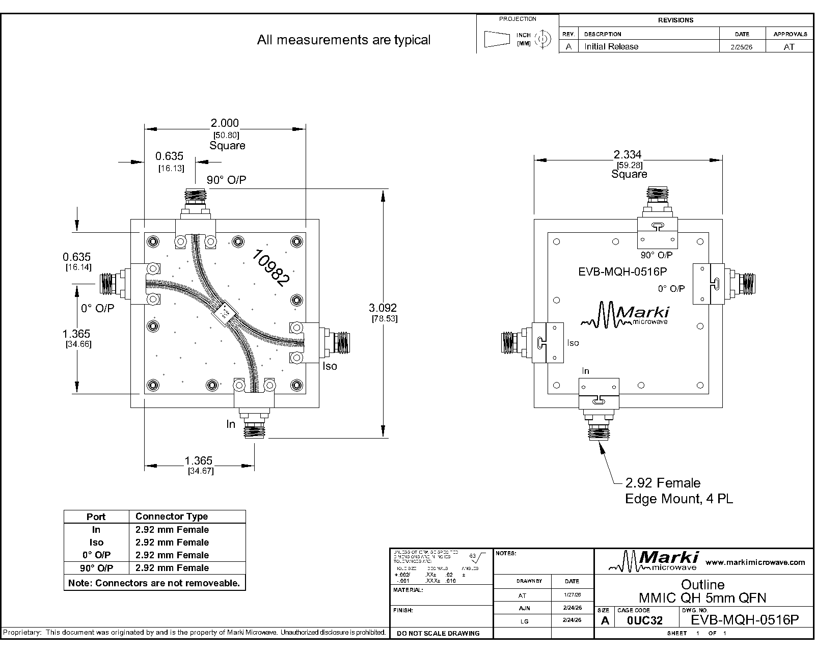
The MQH-0516PSM is a reciprocal MMIC 5-16 GHz quadrature (90°) hybrid which exhibits excellent amplitude balance with broadband quadrature phasing between output ports. The MQH-0516PSM is a reciprocal device, allowing any port to be used as the input without performance degradation. Passive GaAs MMIC technology allows production of smaller constructions that replace larger form factor circuit board constructions. Applications include single sideband upconverters, image rejection downconverters, IQ modulators, balanced amplifiers, microwave correlators, and microwave Butler matrices.

| Part Number | Description | Package | Green Status | Product Lifecycle | Export Classification |
|---|---|---|---|---|---|
| MQH-0516PSM | MMIC 5-16GHz 90° Hybrid Coupler | Plastic QFN | RoHS REACH | Released | EAR99 |
| EVB-MQH-0516P | Evaluation Board, 5 - 16 GHz MMIC 90° Hybrid Coupler | EVB | RoHS REACH | Released | EAR99 |
MQH-0516PSM
MMIC 5-16GHz 90° Hybrid Coupler
| Revision Code | Revision Date | Comment |
|---|---|---|
| - | 2026-05-06 | Initial Release |
MQH-0516PSM
MMIC 5-16GHz 90° Hybrid Coupler
| Port | Function | Description | DC Equivalent Circuit |
|---|---|---|---|
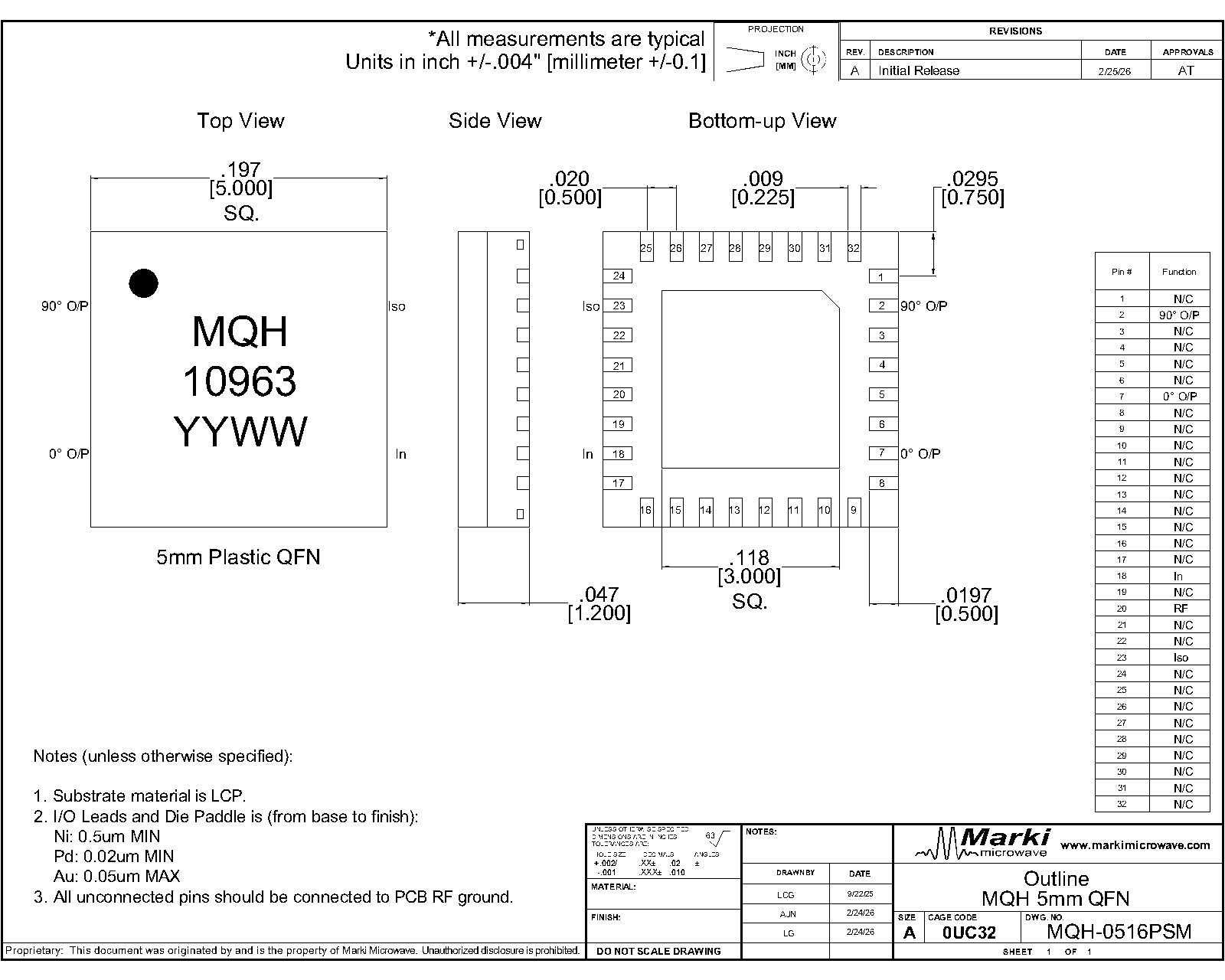
| Pin 18 | Input | Pin 18 is DC short to pin 7 and open to ground. |  |
| Pin 2 | 90° Output | Pin 2 is DC short to pin 23 and open to ground. | |
| Pin 23 | Isolated | Pin 23 is DC short to pin 2 and open to ground. | |
| Pin 7 | 0° Output | Pin 7 is DC short to pin 18 and open to ground. | |
MQH-0516PSM
MMIC 5-16GHz 90° Hybrid Coupler
| Port | Function | Description | DC Equivalent Circuit |
|---|---|---|---|
| Pin 18 | 0° Output | Pin 18 is DC short to pin 7 and open to ground. | |
| Pin 2 | Isolated | Pin 2 is DC short to pin 23 and open to ground. | |
| Pin 23 | 90° Output | Pin 23 is DC short to pin 2 and open to ground. | |
| Pin 7 | Input | Pin 7 is DC short to pin 18 and open to ground. | |
MQH-0516PSM
MMIC 5-16GHz 90° Hybrid Coupler
| Port | Function | Description | DC Equivalent Circuit |
|---|---|---|---|
| Pin 18 | 90° Output | Pin 18 is DC short to pin 7 and open to ground. | |
| Pin 2 | Input | Pin 2 is DC short to pin 23 and open to ground. | |
| Pin 23 | 0° Output | Pin 23 is DC short to pin 2 and open to ground. | |
| Pin 7 | Isolated | Pin 7 is DC short to pin 18 and open to ground. | |
MQH-0516PSM
MMIC 5-16GHz 90° Hybrid Coupler
| Port | Function | Description | DC Equivalent Circuit |
|---|---|---|---|
| Pin 18 | Isolated | Pin 18 is DC short to pin 7 and open to ground. | |
| Pin 2 | 0° Output | Pin 2 is DC short to pin 23 and open to ground. | |
| Pin 23 | Input | Pin 23 is DC short to pin 2 and open to ground. | |
| Pin 7 | 90° Output | Pin 7 is DC short to pin 18 and open to ground. | |
MQH-0516PSM
MMIC 5-16GHz 90° Hybrid Coupler
| Parameter | Maximum Rating | Unit |
|---|---|---|
| Maximum Operating Temperature | 100 | °C |
| Maximum Storage Temperature | 125 | °C |
| Minimum Operating Temperature | -55 | °C |
| Minimum Storage Temperature | -65 | °C |
| Parameter | Details | Rating |
|---|---|---|
| ESD | 250 to < 500 Volts | HBM Class 1A |
| Dimensions | - | 5 x 5 mm |
| Moisture Sensitivity Level | - | MSL 1 |
MQH-0516PSM
MMIC 5-16GHz 90° Hybrid Coupler
| Parameter | Port Configuration | Test Conditions | Minimum Frequency (GHz) | Maximum Frequency (GHz) | Min | Typ | Max | Unit |
|---|---|---|---|---|---|---|---|---|
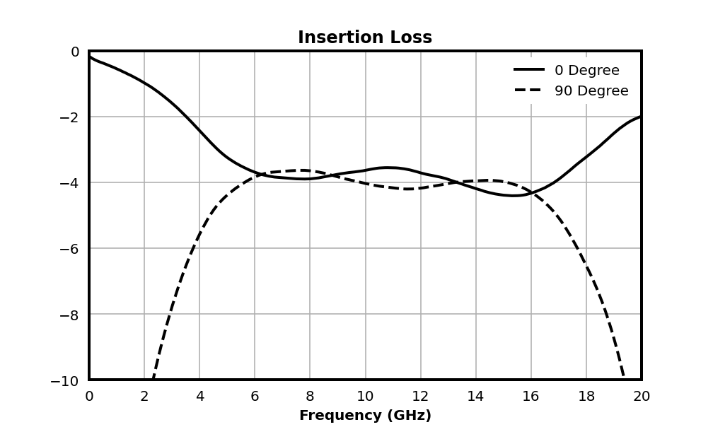
| Insertion Loss | A | - | 5 | 16 | - | 3.8 | - | dB |
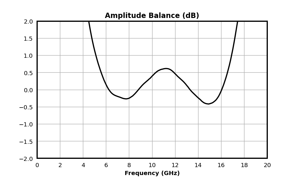
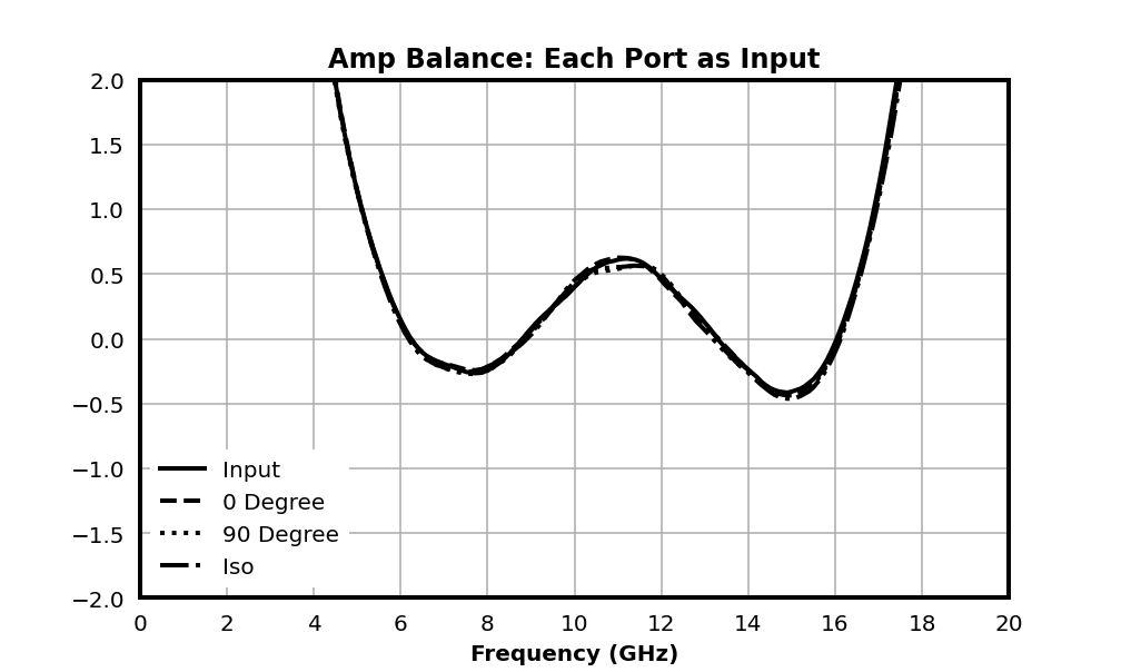
| Amplitude Balance | A | - | 5 | 16 | - | 0.3 | - | dB |
| Coupling | A | - | 5 | 16 | - | 3 | - | dB |
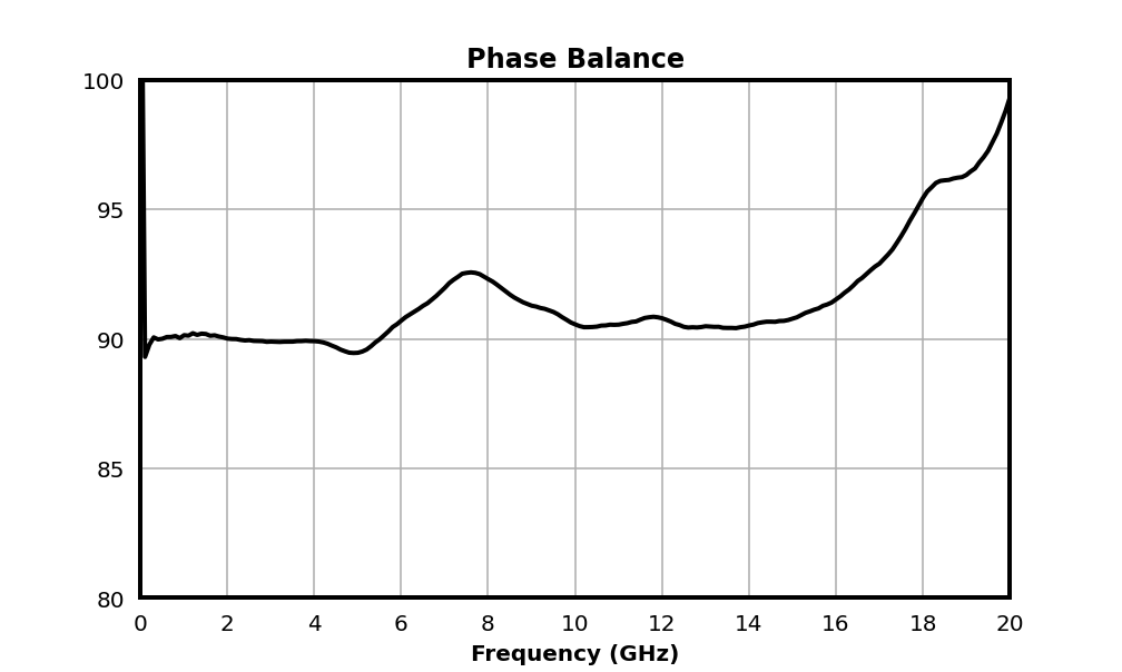
| Nominal Phase Shift | A | - | 5 | 16 | - | 90 | - | ° |
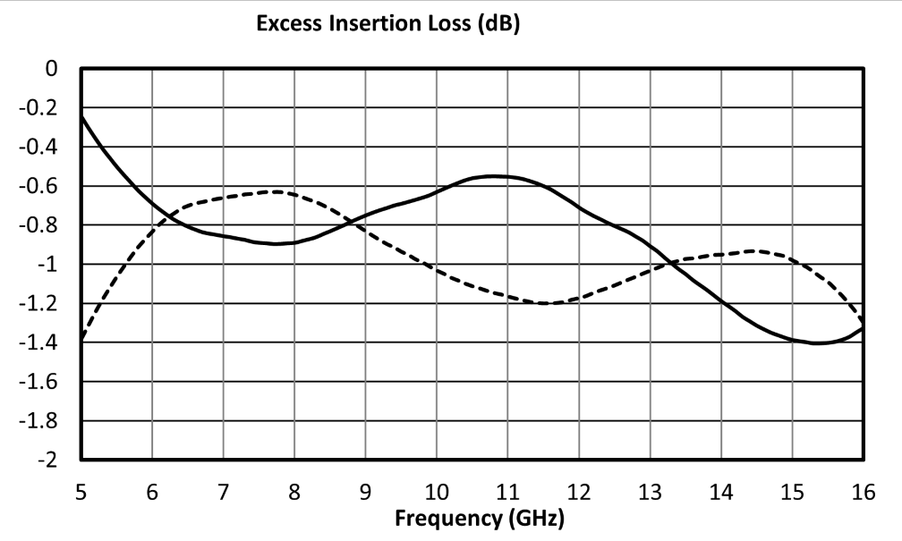
| Excess Insertion Loss 1 | A | - | 5 | 16 | - | 0.8 | - | dB |
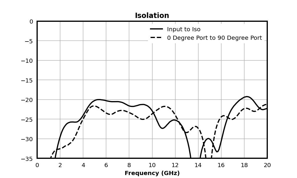
| Isolation | A | - | 5 | 16 | - | 27 | - | dB |
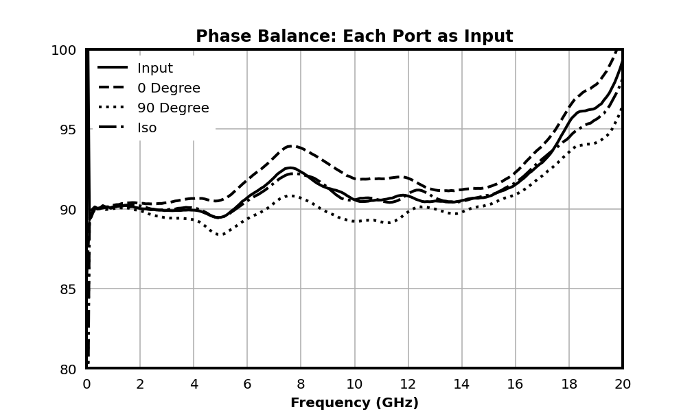
| Phase Balance | A | - | 5 | 16 | - | 3 | - | ° |
| Impedance | - | All Ports | 5 | 16 | - | 50 | - | Ω |
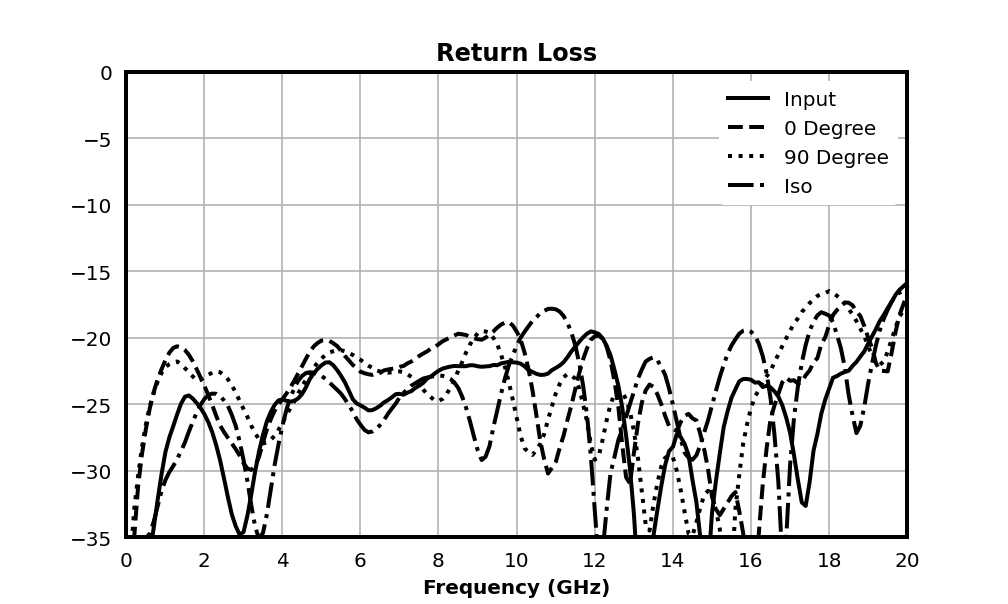
| Return Loss | - | All Ports | 5 | 16 | - | 26 | - | dB |
| Parameter | Port Configuration | Test Conditions | Minimum Frequency (GHz) | Maximum Frequency (GHz) | Min | Typ | Max | Unit |
|---|---|---|---|---|---|---|---|---|
| Insertion Loss | A | - | 5 | 16 | - | 3.8 | - | dB |
| Amplitude Balance | A | - | 5 | 16 | - | 0.3 | - | dB |
| Coupling | A | - | 5 | 16 | - | 3 | - | dB |
| Nominal Phase Shift | A | - | 5 | 16 | - | 90 | - | ° |
| Excess Insertion Loss 1 | A | - | 5 | 16 | - | 0.8 | - | dB |
| Isolation | A | - | 5 | 16 | - | 27 | - | dB |
| Phase Balance | A | - | 5 | 16 | - | 3 | - | ° |
| Impedance | - | All Ports | 5 | 16 | - | 50 | - | Ω |
| Return Loss | - | All Ports | 5 | 16 | - | 26 | - | dB |
[1] Excess Insertion Loss = Input to Output Insertion Loss - 3dB
MQH-0516PSM
MMIC 5-16GHz 90° Hybrid Coupler
Typical performance plots shown for port configuration A. Performance may vary in alternate configurations.
MQH-0516PSM
MMIC 5-16GHz 90° Hybrid Coupler
MQH-0516PSM
MMIC 5-16GHz 90° Hybrid Coupler