Package Information
| Parameter | Details | Rating |
|---|---|---|
| Dimensions | - | 3.81 x 6.10 mm |
| Moisture Sensitivity Level | - | MSL 3 |
Sales: 408-778-9952 | General: 408-778-4200 | Fax: 408-778-4300
Sales & Customer Support: [email protected]
Tech Support: [email protected]
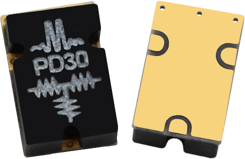
The PD-0030SMG is a surface mount resistive 2-way power divider that features broadband operation from DC to 30 GHz. Resistive power dividers offer 6 dB nominal insertion loss and excellent amplitude and phase balance. Resistive power dividers are not recommended for use as a power combiner due to the lack of isolation.
N/A
N/A
| Part Number | Description | Package | Green Status | Product Lifecycle | Export Classification |
|---|---|---|---|---|---|
| PD-0030SMG | Resistive Power Divider | SMG | REACH RoHS | Released | EAR99 |
| Part Number | Description | Package | Green Status | Product Lifecycle | Export Classification |
|---|---|---|---|---|---|
| PD-0030SMG | Resistive Power Divider | SMG | REACH RoHS | Released | EAR99 |
PD-0030SMG
Resistive Power Divider
| Revision Code | Revision Date | Comment |
|---|---|---|
| - | 2018-05-03 | Datasheet Initial Release |
PD-0030SMG
Resistive Power Divider
| Port | Function | Description | DC Equivalent Circuit |
|---|---|---|---|
| 1 | In/Out 1 | RF input/output 1 of the combiner. | - |
| 2 | In/Out 2 | RF input/output 2 of the combiner. | - |
| 3 | In/Out 3 | RF input/output 3 of the combiner. | - |
PD-0030SMG
Resistive Power Divider
| Parameter | Details | Rating |
|---|---|---|
| Dimensions | - | 3.81 x 6.10 mm |
| Moisture Sensitivity Level | - | MSL 3 |
PD-0030SMG
Resistive Power Divider
Specifications guaranteed from -55 to +100°C, measured in a 50Ω system.
| Parameter | Test Conditions | Minimum Frequency (GHz) | Maximum Frequency (GHz) | Min | Typ | Max | Unit |
|---|---|---|---|---|---|---|---|
| Amplitude Balance | DC-30 GHz | - | - | - | 0.25 | - | dB |
| Excess Insertion Loss 1 | DC-30 GHz | - | - | - | 1 | 3 | dB |
| Input Power | DC-30 GHz | - | - | - | - | 1 | W |
| Nominal Phase Shift | DC-30 GHz | - | - | - | 0 | - | ° |
| Nominal Power Splitting | DC-30 GHz | - | - | - | 6 | - | dB |
| Phase Balance | DC-30 GHz | - | - | - | 3 | - | ° |
| VSWR | DC-30 GHz | - | - | - | 1.6 | - | - |
[1] Excess Insertion Loss = (Input Port to Common Port Insertion Loss) - 6dB
PD-0030SMG
Resistive Power Divider


PD-0030SMG
Resistive Power Divider
Download : Outline 2D Drawing Outline 3D Drawing Outline 3D STP
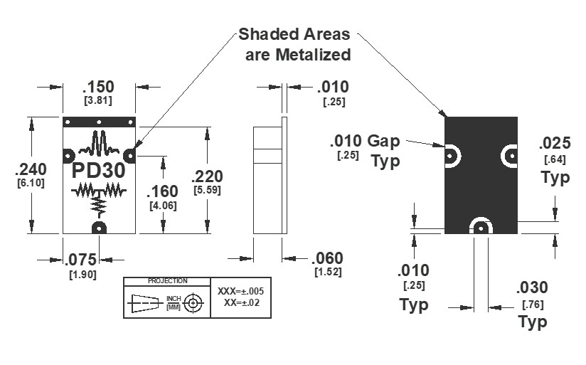
Termination Finish is Gold Flash, 5 to 10 μ-inches, over SolderableElectroless Nickel, 100-200 μ-inches
PD-0030SMG
Resistive Power Divider
Download : Footprint Drawing
