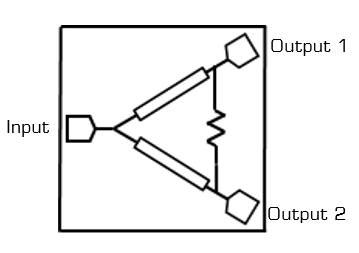
Port Diagram
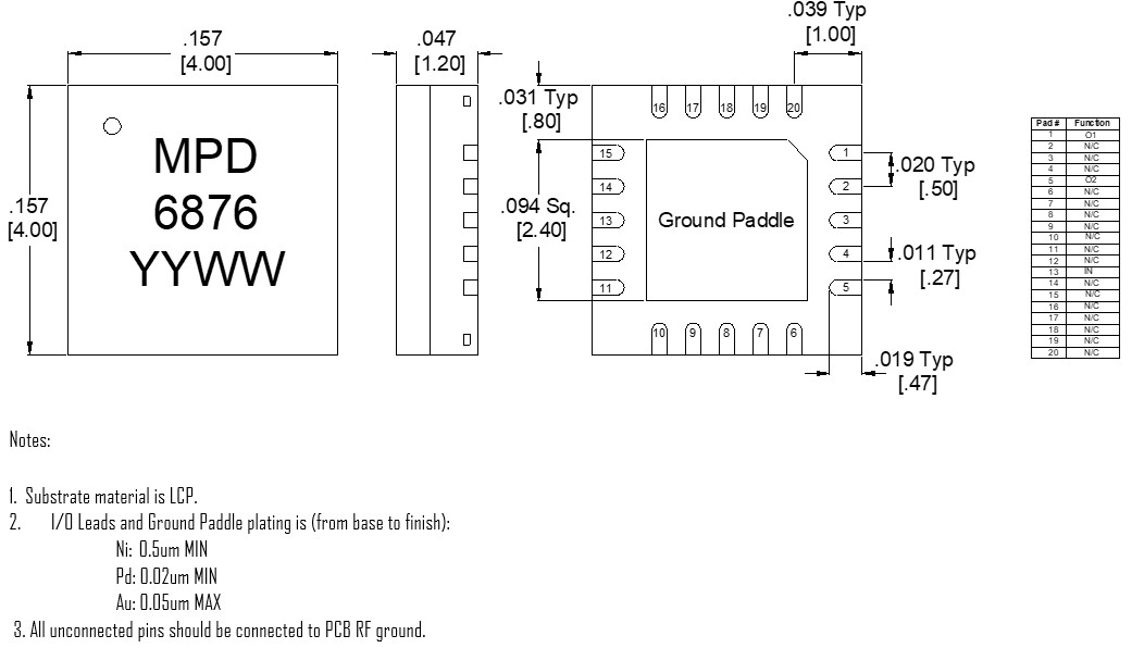
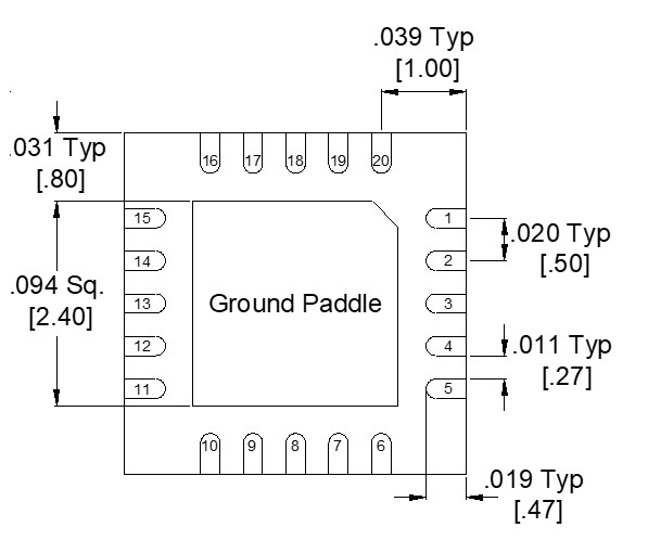
A bottom-up view of the MPD-0226SM’s SM package outline drawing is shown below. The MMIC Power dividers are passive reciprocal devices allowing either power splitting or power combining.
Sales: 408-778-9952 | General: 408-778-4200 | Fax: 408-778-4300
Sales & Customer Support: [email protected]
Tech Support: [email protected]
MPD-0226SM is a MMIC 2-way Wilkinson power divider. Passive GaAs MMIC technology allows production of smaller constructions that replace larger form factor circuit board constructions. Tight fabrication tolerances result in less unit to unit variation than traditional power divider technologies, allowing for accurate simulations using the provided S3P file taken from measured production units. Power dividers are passive reciprocal devices that can be used either as power combiners or as power dividers. Applications include Radar, Satcom, EW and test equipment. The MPD-0226SM is available as a 4 X 4 mm QFN package. Evaluation boards are also available.
N/A
| Part Number | Description | Package | Packing Size | Green Status | Product Lifecycle | Export Classification |
|---|---|---|---|---|---|---|
| MPD-0226SM | 2-26.5 GHz MMIC 2-way Wilkinson Power Divider/Combiner | QFN | - | REACH RoHS | Released | EAR99 |
| EVAL-MPD-0226 | Evaluation Board, 2-26.5 GHz MMIC 2-way Power Divider/Combiner | EVAL | - | REACH RoHS | Released | EAR99 |
| MPD-0226-TR | Tape and Reel, 2-26.5 GHz MMIC 2-way Wilkinson Power Divider/Combiner | QFN | 7" | REACH RoHS | Released | EAR99 |
MPD-0226SM
2-26.5 GHz MMIC 2-way Wilkinson Power Divider/Combiner
| Revision Code | Revision Date | Comment |
|---|---|---|
| - | 2020-06-01 | Initial Datasheet Release |
| A | 2021-01-01 | Specs table update |
| B | 2022-03-01 | Power Handling Specs Updated |
| C | 2025-12-17 | Power Handling Updated |
MPD-0226SM
2-26.5 GHz MMIC 2-way Wilkinson Power Divider/Combiner
A bottom-up view of the MPD-0226SM’s SM package outline drawing is shown below. The MMIC Power dividers are passive reciprocal devices allowing either power splitting or power combining.
| Port | Function | Description | DC Equivalent Circuit |
|---|---|---|---|
| Pad | Ground | SM package ground path is provided through the ground paddle. |  |
| Pin 1 | Output 1 | The output 1 port is DC short to the other two ports and open to ground. |  |
| Pin 13 | Input/common | The common port is DC short to the other two ports and open to ground. | |
| Pin 5 | Output 2 | The output 2 port is DC short to the other two ports and open to ground. | |
MPD-0226SM
2-26.5 GHz MMIC 2-way Wilkinson Power Divider/Combiner
The Absolute Maximum Ratings indicate limits beyond which damage may occur to the device. If these limits are exceeded, the device may be inoperable or have a reduced lifetime.
| Parameter | Maximum Rating | Unit |
|---|---|---|
| DC Current | 60 | mA |
| Maximum Operating Temperature | 100 | °C |
| Maximum Storage Temperature | 125 | °C |
| Minimum Operating Temperature | -55 | °C |
| Minimum Storage Temperature | -65 | °C |
| RF Power Handling as a Power Combiner 1 | 2 | W |
| RF Power Handling as a Power Divider 2 | 20 | W |
[1] Based on 3W failure with out of phase signals at room temperature at 2.5GHz with matched loads.
[2] Based >40W Power handling test as a splitter without failure at room temperature at 2.5GHz with matched loads.
| Parameter | Details | Rating |
|---|---|---|
| ESD | 250 to < 500 Volts | HBM Class 1A |
| Dimensions | - | 4 x 4 mm |
| Moisture Sensitivity Level | - | MSL 1 |
MPD-0226SM
2-26.5 GHz MMIC 2-way Wilkinson Power Divider/Combiner
The electrical specifications apply at TA=+25°C in a 50Ω system. Min and Max limits are guaranteed at TA=+25°C. All measured data is taken from the eval board without de-embedding of the connectors and traces.
| Parameter | Test Conditions | Minimum Frequency (GHz) | Maximum Frequency (GHz) | Min | Typ | Max | Unit |
|---|---|---|---|---|---|---|---|
| Amplitude Balance | - | 2 | 26.5 | - | 0.2 | 0.8 | dB |
| Excess Insertion Loss 1 | - | 2 | 20 | - | 1.5 | 4 | dB |
| Excess Insertion Loss 2 | - | 20 | 26.5 | - | 3 | 6 | dB |
| Impedance | - | - | - | - | 50 | - | Ω |
| Isolation | - | 2 | 26.5 | - | 20 | - | dB |
| Nominal Phase Shift | - | 2 | 26.5 | - | 0 | - | ° |
| Nominal Power Splitting | - | 2 | 26.5 | - | 3 | - | dB |
| Phase Balance | - | 2 | 26.5 | - | 2 | 8.5 | ° |
| VSWR | - | 2 | 26.5 | - | 1.25 | - | - |
[1][2] Excess Insertion Loss = (Input Port to Common Port Insertion Loss) - 3dB
MPD-0226SM
2-26.5 GHz MMIC 2-way Wilkinson Power Divider/Combiner


MPD-0226SM
2-26.5 GHz MMIC 2-way Wilkinson Power Divider/Combiner
MPD-0226SM
2-26.5 GHz MMIC 2-way Wilkinson Power Divider/Combiner
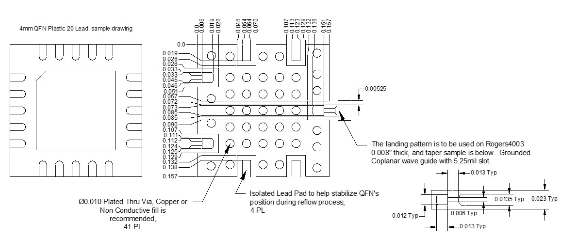
Download : Footprint Drawing
MPD-0226SM
2-26.5 GHz MMIC 2-way Wilkinson Power Divider/Combiner