Rev: A | Copyright © 2020, 2022 Marki Microwave LLC.

General Description

NLTL-6796SM is a MMIC non-linear transmission line (NLTL) based comb generator. This NLTL offers excellent phase noise performance over a 500MHz to 3.5 GHz input frequency range with output tones beyond 40 GHz. NLTL-6796SM is fabricated with GaAs Schottky diode-based varactors and packaged into a surface mount 6mm QFN.
Features

  • Low Phase Noise
  • Broadband Input Frequencies
  • No External DC Bias Required

Functional Block Diagram

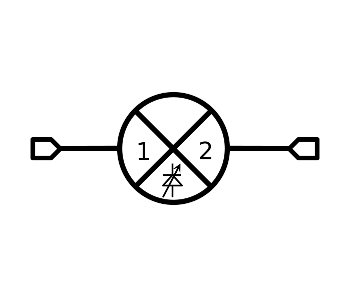
Block Diagram
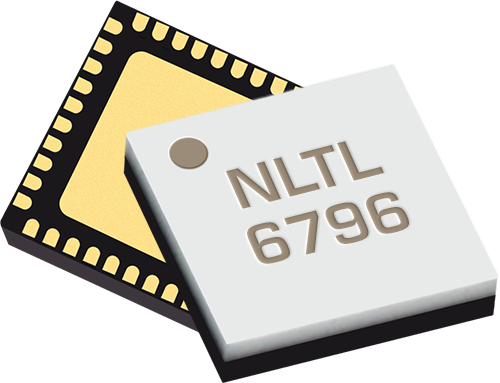
Photo of NLTL-6796SM

Electrical Performance Summary

ParameterTypUnit
Input Power 20dBm
Output Frequency Range 0.5 to 50GHz
Input Frequency Range 0.5 to 3.5GHz

Summary only – refer to the Electrical Specifications, Absolute Maximum Ratings, and Recommended Operating Range tables for complete details.

Part Ordering Options

Part NumberDescriptionPackageGreen StatusProduct LifecycleExport Classification
NLTL-6796SMGaAs MMIC Non-Linear Transmission LineQFN

RoHS

REACH

ReleasedEAR99
EVAL-NLTL-6796Evaluation Board, GaAs MMIC 0.5-3.5 GHz Non-Linear Transmission LineEVAL

RoHS

REACH

ReleasedEAR99

Table Of Contents

Typical Performance Plots: Harmonic Output Power w/ Sine Input

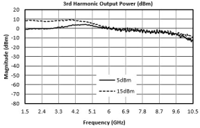
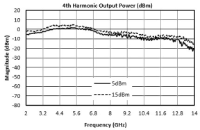
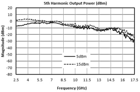
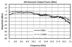
Input power levels refer to drive level going into the NLTL chain input in Application Circuit. Square wave plots are referenced to drive level entering the square wave driver amplifier, not the output power of the amplifiers.

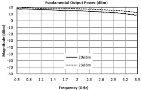
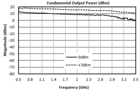
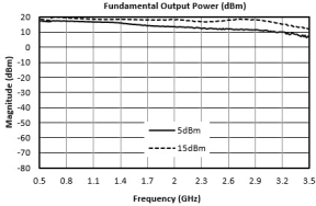
Fundamental Output Power (dBm) graph for NLTL-6796SM
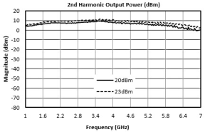
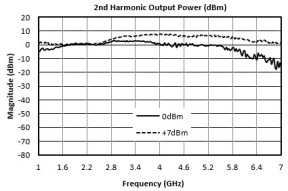
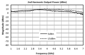
2nd Harmonic Output Power (dBm) graph for NLTL-6796SM
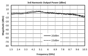
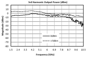
3rd Harmonic Output Power (dBm) graph for NLTL-6796SM
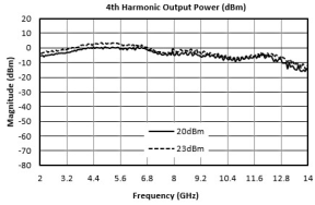
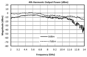
4th Harmonic Output Power (dBm) graph for NLTL-6796SM
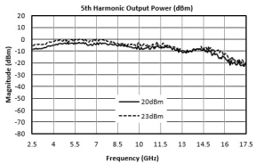
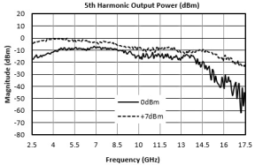
5th Harmonic Output Power (dBm) graph for NLTL-6796SM
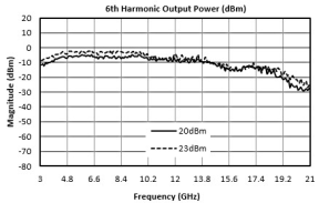
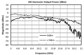
6th Harmonic Output Power (dBm) graph for NLTL-6796SM
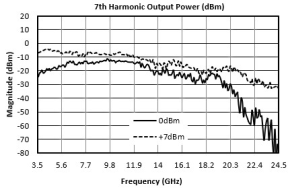
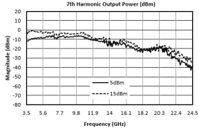
7th Harmonic Output Power (dBm) graph for NLTL-6796SM
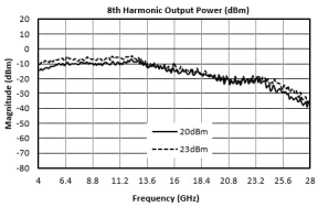
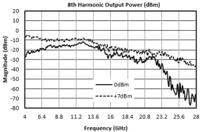
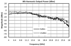
8th Harmonic Output Power (dBm) graph for NLTL-6796SM
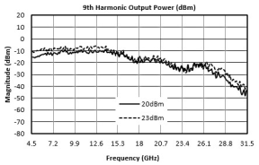
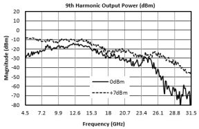
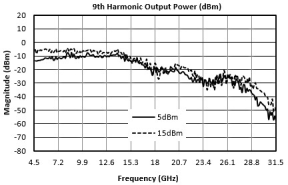
9th Harmonic Output Power (dBm) graph for NLTL-6796SM
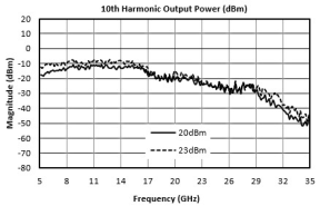
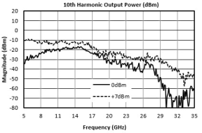
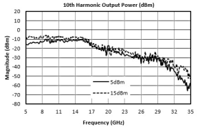
10th Harmonic Output Power (dBm) graph for NLTL-6796SM
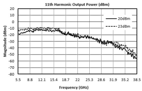
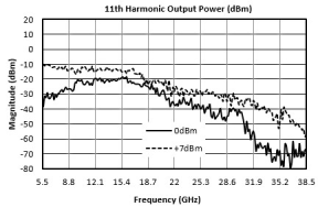
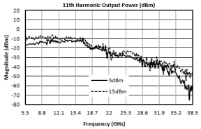
11th Harmonic Output Power (dBm) graph for NLTL-6796SM
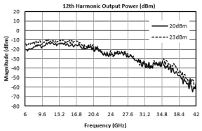
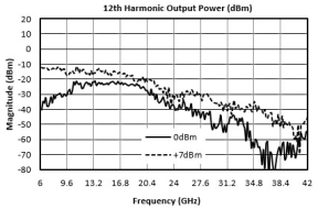
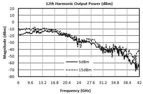
12th Harmonic Output Power (dBm) graph for NLTL-6796SM
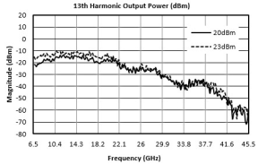
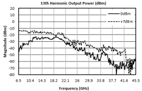
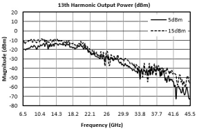
13th Harmonic Output Power (dBm) graph for NLTL-6796SM
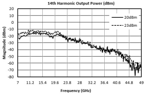
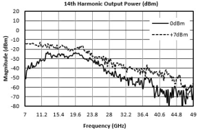
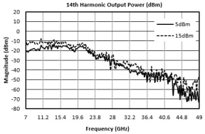
14th Harmonic Output Power (dBm) graph for NLTL-6796SM
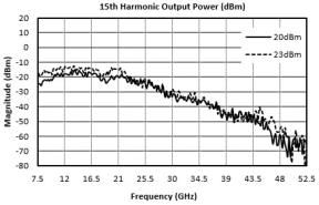
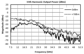
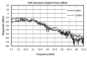
15th Harmonic Output Power (dBm) graph for NLTL-6796SM
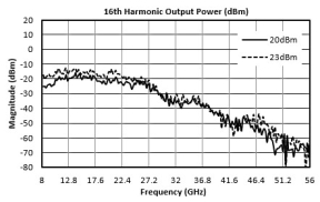
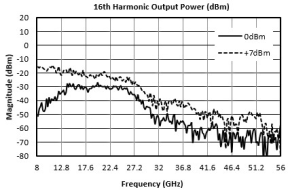
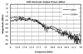
16th Harmonic Output Power (dBm) graph for NLTL-6796SM
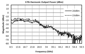
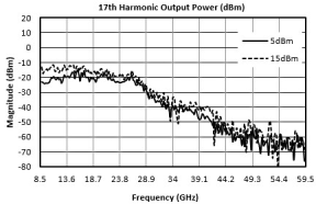
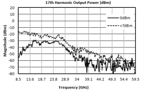
17th Harmonic Output Power (dBm) graph for NLTL-6796SM
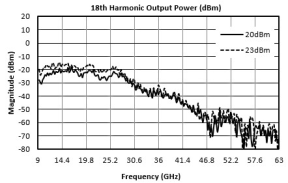
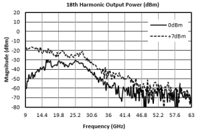
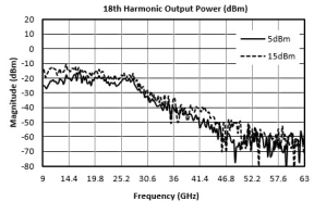
18th Harmonic Output Power (dBm) graph for NLTL-6796SM
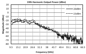
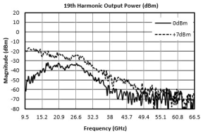
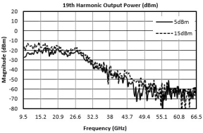
19th Harmonic Output Power (dBm) graph for NLTL-6796SM

Typical Performance Plots: Harmonic Output Power w/ Square Wave from APM-7098PA

Input power levels refer to drive level going into the NLTL chain input in Application Circuit. Square wave plots are referenced to drive level entering the square wave driver amplifier, not the output power of the amplifiers.

Fundamental Output Power (dBm) graph for NLTL-6796SM
2nd Harmonic Output Power (dBm) graph for NLTL-6796SM
3rd Harmonic Output Power (dBm) graph for NLTL-6796SM
4th Harmonic Output Power (dBm) graph for NLTL-6796SM
5th Harmonic Output Power (dBm) graph for NLTL-6796SM
6th Harmonic Output Power (dBm) graph for NLTL-6796SM
7th Harmonic Output Power (dBm) graph for NLTL-6796SM
8th Harmonic Output Power (dBm) graph for NLTL-6796SM
9th Harmonic Output Power (dBm) graph for NLTL-6796SM
10th Harmonic Output Power (dBm) graph for NLTL-6796SM
11th Harmonic Output Power (dBm) graph for NLTL-6796SM
12th Harmonic Output Power (dBm) graph for NLTL-6796SM
13th Harmonic Output Power (dBm) graph for NLTL-6796SM
14th Harmonic Output Power (dBm) graph for NLTL-6796SM
15th Harmonic Output Power (dBm) graph for NLTL-6796SM
16th Harmonic Output Power (dBm) graph for NLTL-6796SM
17th Harmonic Output Power (dBm) graph for NLTL-6796SM
18th Harmonic Output Power (dBm) graph for NLTL-6796SM
19th Harmonic Output Power (dBm) graph for NLTL-6796SM

Typical Performance Plots: Harmonic Output Power w/ Square Wave from ADM1-0026PA

Input power levels refer to drive level going into the NLTL chain input in Application Circuit. Square wave plots are referenced to drive level entering the square wave driver amplifier, not the output power of the amplifiers.

Fundamental Output Power (dBm) graph for NLTL-6796SM
2nd Harmonic Output Power (dBm) graph for NLTL-6796SM
3rd Harmonic Output Power (dBm) graph for NLTL-6796SM
4th Harmonic Output Power (dBm) graph for NLTL-6796SM
5th Harmonic Output Power (dBm) graph for NLTL-6796SM
6th Harmonic Output Power (dBm) graph for NLTL-6796SM
7th Harmonic Output Power (dBm) graph for NLTL-6796SM
8th Harmonic Output Power (dBm) graph for NLTL-6796SM
9th Harmonic Output Power (dBm) graph for NLTL-6796SM
10th Harmonic Output Power (dBm) graph for NLTL-6796SM
11th Harmonic Output Power (dBm) graph for NLTL-6796SM
12th Harmonic Output Power (dBm) graph for NLTL-6796SM
13th Harmonic Output Power (dBm) graph for NLTL-6796SM
14th Harmonic Output Power (dBm) graph for NLTL-6796SM
15th Harmonic Output Power (dBm) graph for NLTL-6796SM
16th Harmonic Output Power (dBm) graph for NLTL-6796SM
17th Harmonic Output Power (dBm) graph for NLTL-6796SM
18th Harmonic Output Power (dBm) graph for NLTL-6796SM
19th Harmonic Output Power (dBm) graph for NLTL-6796SM

Typical Performance Plots: 5th Harmonic Output Power vs Bias Resistor

Input power levels refer to drive level going into the NLTL chain input in Application Circuit. Square wave plots are referenced to drive level entering the square wave driver amplifier, not the output power of the amplifiers.

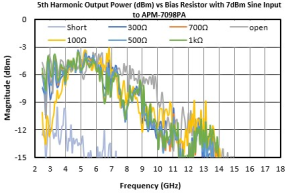
5th Harmonic Output Power vs Bias Resistor with 7dBm Sine Input to APM-7098PA (dBm) graph for NLTL-6796SM
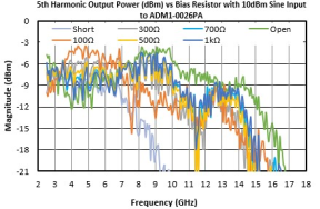
5th Harmonic Output Power vs Bias Resistor with 10dBm Sine Input to ADM1-0026PA (dBm) graph for NLTL-6796SM
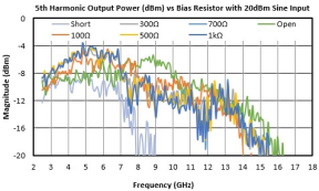
5th Harmonic Output Power vs Bias Resistor with 20dBm Sine Input (dBm) graph for NLTL-6796SM

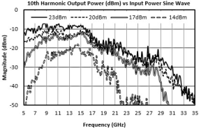
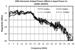
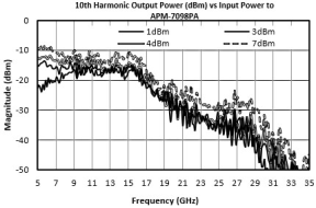
Typical Performance Plots: 10th Harmonic Output Power vs Input Power

Input power levels refer to drive level going into the NLTL chain input in Application Circuit. Square wave plots are referenced to drive level entering the square wave driver amplifier, not the output power of the amplifiers.

10th Harmonic Output Power vs Input Power Sine Wave (dBm) graph for NLTL-6796SM
10th Harmonic Output Power vs Input Power to ADM1-0026PA (dBm) graph for NLTL-6796SM
10th Harmonic Output Power vs Input Power to APM-7098PA (dBm) graph for NLTL-6796SM

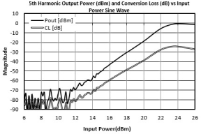
Typical Performance Plots: Conversion Loss and Output Power vs Input Power

Input power levels refer to drive level going into the NLTL chain input in Application Circuit. Square wave plots are referenced to drive level entering the square wave driver amplifier, not the output power of the amplifiers.

5th Harmonic Output Power (dBm) and Conversion Loss (dB) vs Input Power Sine Wave graph for NLTL-6796SM
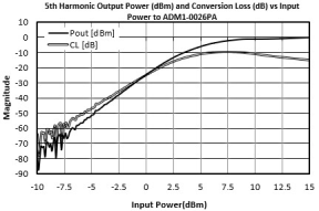
5th Harmonic Output Power (dBm) and Conversion Loss (dB) vs Input Power to ADM1-0026PA graph for NLTL-6796SM
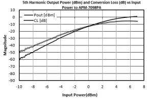
5th Harmonic Output Power (dBm) and Conversion Loss (dB) vs Input Power to APM-7098PA graph for NLTL-6796SM

Typical Performance Plots: Harmonic Magnitude vs Bias Resistor

Input power levels refer to drive level going into the NLTL chain input in Application Circuit. Square wave plots are referenced to drive level entering the square wave driver amplifier, not the output power of the amplifiers.

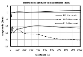
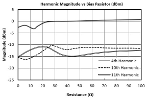
Harmonic Magnitude vs Bias Resistor (dBm) graph for NLTL-6796SM

Typical Performance Plots: Time and Frequency Domain Plots

Input power levels refer to drive level going into the NLTL chain input in Application Circuit. Square wave plots are referenced to drive level entering the square wave driver amplifier, not the output power of the amplifiers.

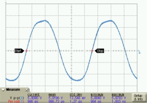
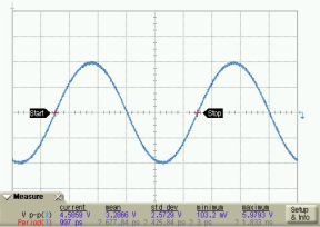
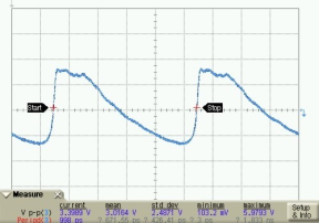
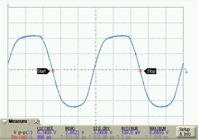
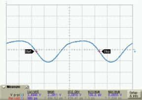
Into NLTL graph for NLTL-6796SM
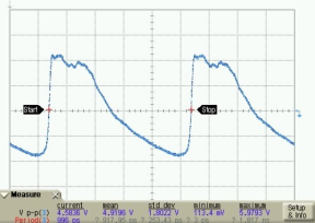
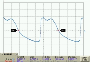
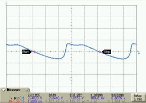
Out of NLTL graph for NLTL-6796SM
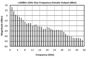
+20dBm 1GHz Sine Frequency Domain Output (dBm) graph for NLTL-6796SM
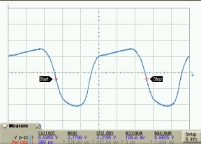
Into NLTL graph for NLTL-6796SM
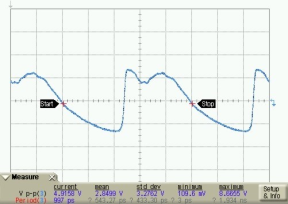
Out of NLTL graph for NLTL-6796SM
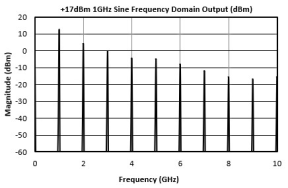
+17dBm 1GHz Sine Frequency Domain Output (dBm) graph for NLTL-6796SM
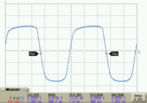
Out of ADM1-0026PA (Into NLTL) graph for NLTL-6796SM
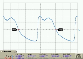
Out of NLTL graph for NLTL-6796SM
+15dBm 1GHz into ADM1-0026PA Frequency Domain Output (dBm) graph for NLTL-6796SM
Out of ADM1-0026PA (Into NLTL) graph for NLTL-6796SM
Out of NLTL graph for NLTL-6796SM
+10dBm 1GHz into ADM1-0026PA Frequency Domain Output (dBm) graph for NLTL-6796SM
Out of APM-7098PA (Into NLTL) graph for NLTL-6796SM
Out of NLTL graph for NLTL-6796SM
+7dBm 1GHz into APM-7098PA Frequency Domain Output (dBm) graph for NLTL-6796SM
Out of APM-7098PA (Into NLTL) graph for NLTL-6796SM
Out of NLTL graph for NLTL-6796SM
+0dBm 1GHz into APM-7098PA Frequency Domain Output (dBm) graph for NLTL-6796SM

Specifications

Electrical Specifications

The electrical specifications apply at TA=+25°C in a 50Ω system. Typical data shown is for the NLTL used in the forward direction with a +20 dBm 1GHz sine wave input and no bias resistor (open circuit) unless otherwise stated. Square Wave input generated using either the ADM1-0026PA or the APM-7098PA amplifier at +7V/-0.3V and +8V/+8V respectively. Min and Max limits apply only to our connectorized units and are guaranteed at TA=+25°C. All bare die are 100% DC tested and visually inspected.

ParameterTest ConditionsMinimum
Frequency
(GHz)
Maximum
Frequency
(GHz)
MinTypMaxUnit
Highest Frequency Harmonic Output 11.5 GHz Input
- --52.5-GHz
Highest Frequency Harmonic Output 21 GHz Input
- --47-GHz
Highest Frequency Harmonic Output 32 GHz Input
- --46-GHz
Highest Frequency Harmonic Output 43.5 GHz Input
- --28-GHz
Highest Frequency Harmonic Output 5500 MHz Input
- --22.5-GHz
Input Frequency Range -- -0.5-3.5GHz
Input Power 6-- --20-dBm
Output Frequency Range -- -0.5-50GHz

[1][2][3][4][5] The Highest Frequency Harmonic Output was determined as the highest frequency harmonic that was above a -60dBm threshold as seen on a spectrum analyzer.

[6] Input power to square wave driver amps is lower but high enough to saturate the amplifier. Power levels in square wave plots refer to input power to the amplifier, not the amplifier’s output power.

The Recommended Operating Conditions indicate the limits inside which the device should be operated to guarantee the performance given in Electrical Specifications. Operating outside these limits may not necessarily cause damage to the device, but the performance may degrade outside the limits of the electrical specifications. For limits, above which damage may occur, see Absolute Maximum Ratings.

ParameterMinNominalMaxUnit
Input Power 132028dBm
Ambient Temperature -5525100°C

Absolute Maximum Ratings

The Absolute Maximum Ratings indicate limits beyond which damage may occur to the device. If these limits are exceeded, the device may be inoperable or have a reduced lifetime.

ParameterMaximum RatingUnit
Maximum Operating Temperature 100°C
Maximum Storage Temperature 125°C
Minimum Operating Temperature -55°C
Minimum Storage Temperature -65°C
Power Handling, at any Port 33dBm

Package Information

ParameterDetailsRating
ESD250 to < 500 VoltsHBM Class 1A
Dimensions-6 x 6 mm
Moisture Sensitivity Level-MSL 1

Sequencing Requirements

This is a passive NLTL that requires no external DC bias. Self-bias of the diodes is sufficient for operation. It is not required, but is recommended to provide a 50Ω termination to each port before applying RF power.

Port Configuration and Functions

Port Diagram

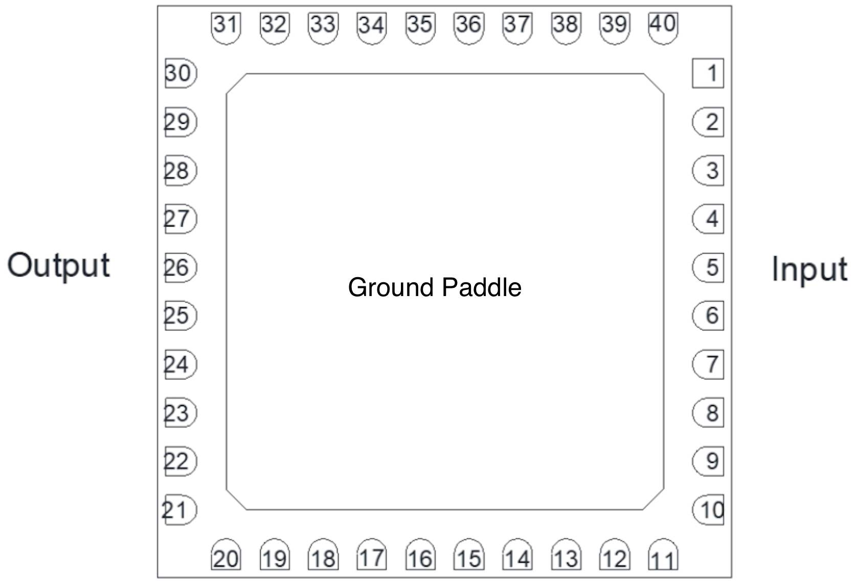
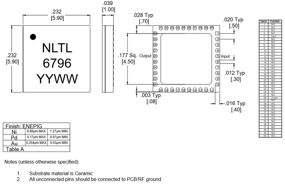
A bottom-up view of the NLTL-6796’s SM package outline drawing is shown below. The NLTL should only be used in the forward direction, with the input and output ports given in Port Functions.

Diagram of the port configuration for NLTL-6796SM

Port Functions

PortFunctionDescriptionDC Equivalent
Circuit
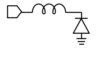
GNDGround SM package ground path is provided through the ground paddle.Equivalent circuit for the Ground
Pin 26Output 2x Input Frequency output port. Pin 26 is diode connected and AC matched to 50Ω.Equivalent circuit for the Output
Pin 5Input Input 1x Frequency Port. Pin 5 is diode connected and AC matched to 50Ω.Equivalent circuit for the Input

Operation

Application Information

Nltl 6796 Sm App Information

Detailed Description

The NLTL-6796SM belongs to Marki Microwave’s NLTL family of multipliers and non-linear transmission lines. The NLTL product line consists of passive GaAs MMIC non-linear transmission lines designed and fabricated with GaAs Schottky diode-based varactors. NLTLs create an impulse train of harmonics of the fundamental input frequency. The NLTL is capable of generating outputs up to and beyond 40 GHz. The NLTL-6796SM is a 6 mm QFN and the EVAL-NLTL-6796 is a connectorized module with the QFN reflowed onto a PCB.

Port 1 supports up to 3.5GHz input signals. Port 2 outputs integer multiples of the input signal (i.e., x2, x3, x4, etc.) up to a maximum of ~50 GHz given a -60dBm threshold and +20dBm input power. Higher harmonics are generated but at a lower efficiency.

The operating conditions of the NLTL are extremely important to optimize performance. High power inputs will increase the output power observed; however, the conversion efficiency will decrease. This is increasingly true for higher input frequencies and at input powers above the recommended limit. Optimal conversion efficiency of the NLTL is achieved using a square wave input with a fast rise time. Doing so causes a degradation in the 2nd output harmonic but otherwise improves the conversion efficiency at all other harmonics. It is for this reason that the typical performance plots are shown driven with a sine wave input as well as with two amplifiers, the ADM1-0026PA, a square wave driver amp, and the APM-7098PA, a low phase noise amplifier. Typical Performance Plots: Harmonic Magnitude vs Bias Resistor shows the results of these driver amplifiers in time and frequency domain.

NLTL-6796SM requires no external DC bias. The self-bias of the diodes caused by the rectified RF input signal is sufficient for operation. For the best performance, optimization of the DC return path through a bias resistor is recommended for each specific application to optimize the harmonic output power distribution.

The phase noise of a non-linear transmission line is outstanding. If verification of performance is necessary, the application circuit used and input conditions are extremely important. NLTLs are AM sensitive. If there is excessive AM noise on the input of the NLTL, observing the output of the NLTL will show excessive PM/phase noise because of the high AM to PM conversion property of NLTLs.

Application Circuit Description

Nltl 6796 Sm Application CircuitEval Nltl 6796 Application Circuit

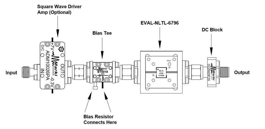
DC Path to Ground — An RF choke followed by a bias resistor should be used to provide a DC path to ground on the input port of the NLTL SM package. The current through the resistor will create Johnson/white noise; a shunt capacitor (for example 1uF) is used to filter noise generated by the resistor. This forms the circuit which self-biases the NLTL. The DC return to ground removes DC rectified current created by high power RF signal injection. A conical coil inductor is recommended to push the self-resonance frequency of the inductor past the operating bandwidth of the NLTL. The recommended inductance value of the conical coil inductor is 50nH or higher. If using a connectorized application setup, a bias tee will provide a DC path to ground and the NLTL can be biased with an additional resistor on the bias tee. See Typical Performance Plots: 5th Harmonic Output Power vs Bias Resistor for output power vs bias resistor plots.

Blocking Capacitor — A DC blocking capacitor on the output of the NLTL-6796SM’s integrated circuit prevents unwanted DC current flow through to the output. If there is a DC signal on the input, place a DC block or bias tee on the input to avoid disrupting the self-biasing of the diodes.

Mechanical Data

Outline Drawing

Download : Outline 2D Drawing Outline 3D Drawing Outline 3D STP

Outline Drawing

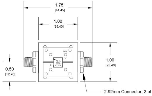
Evaluation Board

Evaluation Board - Outline Drawing

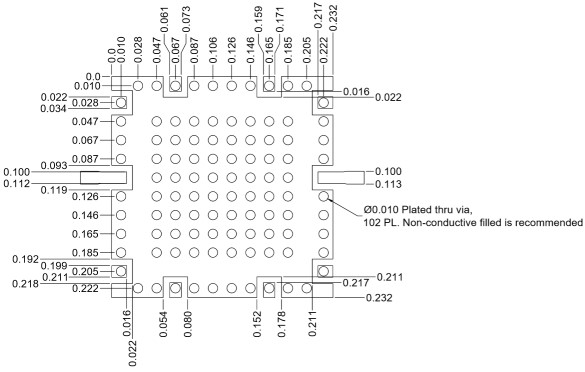
Outline Drawing

Evaluation Board - Application Circuit

Application Circuit for EVAL-NLTL-6796

Revision History

Revision CodeRevision DateComment
-2020-02-01Initial Release
A2022-10-01Recommended Input Power Updated

DISCLAIMER

MARKI MICROWAVE, LLC., (“MARKI”) PROVIDES TECHNICAL SPECIFICATIONS AND DATA (INCLUDING DATASHEETS), APPLICATION OR OTHER DESIGN ADVICE, WEB TOOLS, AND OTHER INFORMATION AND RESOURCES “AS IS” AND WITH ALL FAULTS. MARKI DISCLAIMS ALL WARRANTIES, EXPRESS OR IMPLIED, INCLUDING, WITHOUT LIMITATION, ANY IMPLIED WARRANTIES OF MERCHANTABILITY, FITNESS FOR A PARTICULAR PURPOSE, OR NON-INFRINGEMENT.

These resources are intended for developers skilled in the art designing with Marki products. You are solely responsible for (1) selecting the appropriate products for your application, (2) designing, validating, and testing your application, and (3) ensuring your application meets applicable standards and other requirements. Marki makes no guarantee regarding the suitability of its products for any particular purpose, nor does Marki assume any liability whatsoever arising out of your use or application of any Marki product.

Marki grants you permission to use these resources only for development of an application that uses Marki products. Other reproduction or use of these resources is strictly prohibited. No license is granted to any other Marki intellectual property or to any third-party intellectual property. Marki reserves the right to make changes to the product(s) or information contained herein without notice.

MARKI MICROWAVE, M wave logo, FastSwitch, and T3 MIXER are trademarks or registered trademarks of Marki Microwave, LLC. All other trademarks used are the property of their respective owners.

© 2020, 2022, Marki Microwave, LLC