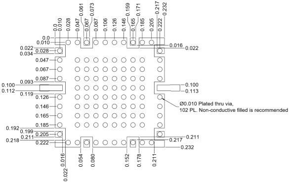
Port Diagram
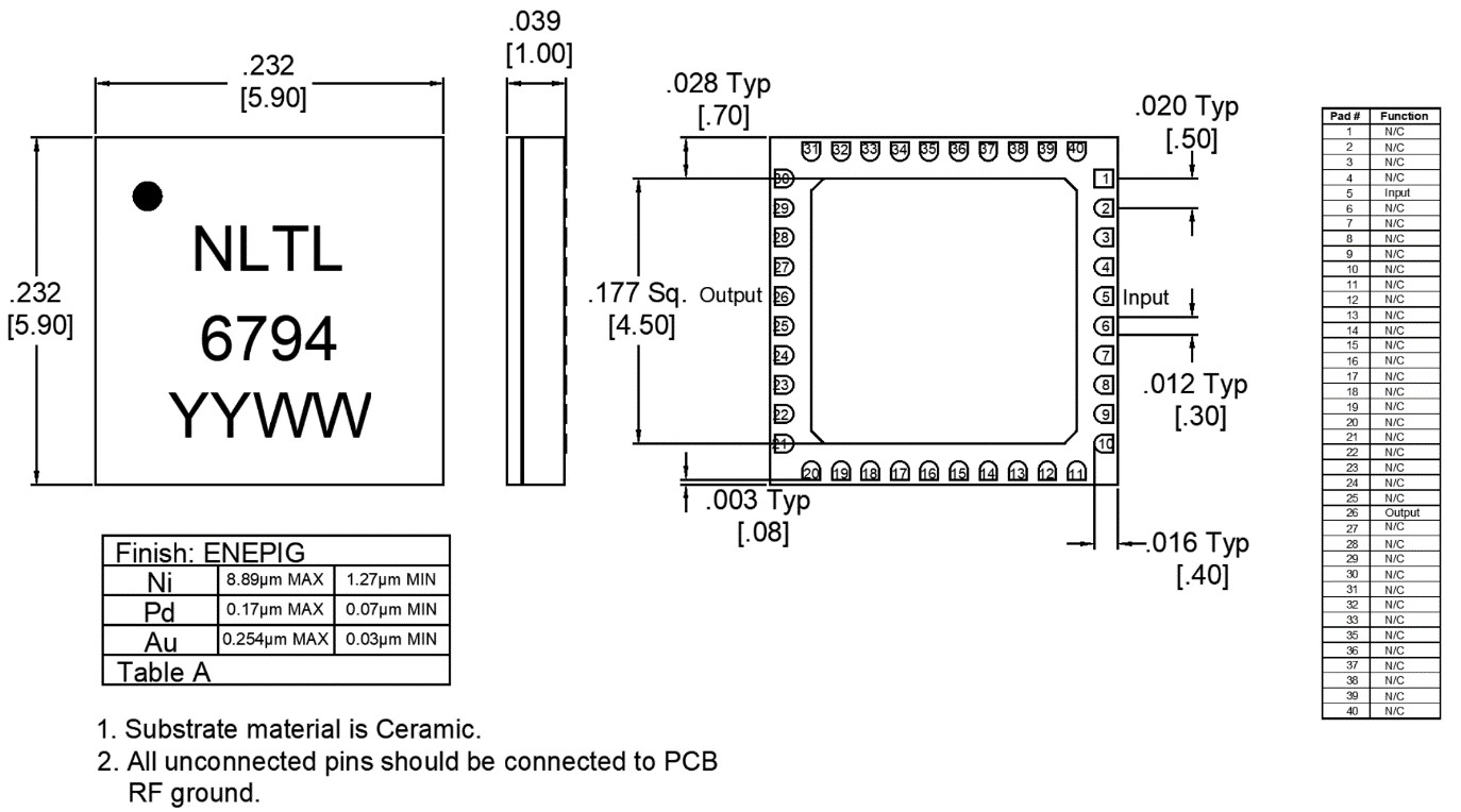
A bottom-up view of the NLTL-6794’s SM package outline drawing is shown below. The NLTL should only be used in the forward direction, with the input and output ports given in Port Functions.

Sales: 408-778-9952 | General: 408-778-4200 | Fax: 408-778-4300
Sales & Customer Support: [email protected]
Tech Support: [email protected]
NLTL-6794SM is a MMIC non-linear transmission line (NLTL) based comb generator. This NLTL offers excellent phase noise performance over a low 100MHz to 1 GHz input frequency range with output tones beyond 30 GHz. NLTL-6794SM is fabricated with GaAs Schottky diode-based varactors and packaged into a surface mount 6x6 mm² QFN.

| Part Number | Description | Package | Green Status | Product Lifecycle | Export Classification |
|---|---|---|---|---|---|
| NLTL-6794SM | GaAs MMIC Non-Linear Transmission Line | QFN | RoHS REACH | Released | EAR99 |
| EVAL-NLTL-6794 | Evaluation Board, GaAs MMIC 0.1-1 GHz Non-Linear Transmission Line | EVAL | RoHS REACH | Released | EAR99 |
NLTL-6794SM
GaAs MMIC Non-Linear Transmission Line
| Revision Code | Revision Date | Comment |
|---|---|---|
| - | 2019-12-01 | Initial Release |
| A | 2022-01-01 | Phase Noise Plot Added |
| B | 2022-10-01 | Recommended Input Power Updated |
NLTL-6794SM
GaAs MMIC Non-Linear Transmission Line
A bottom-up view of the NLTL-6794’s SM package outline drawing is shown below. The NLTL should only be used in the forward direction, with the input and output ports given in Port Functions.
| Port | Function | Description | DC Equivalent Circuit |
|---|---|---|---|
| GND | Ground | SM package ground path is provided through the ground paddle. |  |
| Pin 26 | Output | 2x Input Frequency output port. Pin 26 is diode connected and AC matched to 50Ω. |  |
| Pin 5 | Input | Input 1x Frequency Port. Pin 5 is diode connected and AC matched to 50Ω. | |
NLTL-6794SM
GaAs MMIC Non-Linear Transmission Line
The Absolute Maximum Ratings indicate limits beyond which damage may occur to the device. If these limits are exceeded, the device may be inoperable or have a reduced lifetime.
| Parameter | Maximum Rating | Unit |
|---|---|---|
| Maximum Operating Temperature | 100 | °C |
| Maximum Storage Temperature | 125 | °C |
| Minimum Operating Temperature | -55 | °C |
| Minimum Storage Temperature | -65 | °C |
| Power Handling, at any Port | 33 | dBm |
| Parameter | Details | Rating |
|---|---|---|
| ESD | 250 to < 500 Volts | HBM Class 1A |
| Dimensions | - | 6 x 6 mm |
| Moisture Sensitivity Level | - | MSL 1 |
The Recommended Operating Conditions indicate the limits inside which the device should be operated to guarantee the performance given in Electrical Specifications. Operating outside these limits may not necessarily cause damage to the device, but the performance may degrade outside the limits of the electrical specifications. For limits, above which damage may occur, see Absolute Maximum Ratings.
| Parameter | Min | Nominal | Max | Unit |
|---|---|---|---|---|
| Ambient Temperature | -55 | 25 | 100 | °C |
| Input Power | - | 20 | 28 | dBm |
NLTL-6794SM
GaAs MMIC Non-Linear Transmission Line
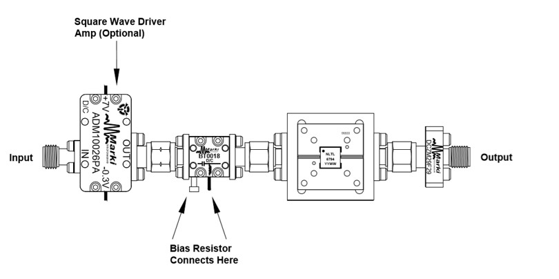
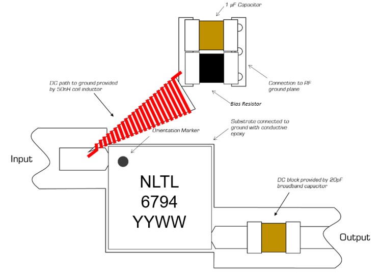
The electrical specifications apply at TA=+25°C in a 50Ω system. Typical data shown is for the NLTL used in the forward direction with a +20 dBm 250MHz sine wave input and no bias resistor (open circuit) unless otherwise stated. Square Wave input generated using either the ADM1-0026PA or the APM-7098PA amplifier at +7V/-0.3V and +8V/+8V respectively. Min and Max limits apply only to our connectorized units and are guaranteed at TA=+25°C. All bare die are 100% DC tested and visually inspected.
| Parameter | Test Conditions | Minimum Frequency (GHz) | Maximum Frequency (GHz) | Min | Typ | Max | Unit |
|---|---|---|---|---|---|---|---|
| Highest Frequency Harmonic Output 1 | 100 MHz Input | - | - | - | 6.1 | - | GHz |
| Highest Frequency Harmonic Output 2 | 1 GHz Input | - | - | - | 22 | - | GHz |
| Highest Frequency Harmonic Output 3 | 250 MHz Input | - | - | - | 23.25 | - | GHz |
| Highest Frequency Harmonic Output 4 | 500 MHz Input | - | - | - | 29.5 | - | GHz |
| Highest Frequency Harmonic Output 5 | 750 MHz Input | - | - | - | 27 | - | GHz |
| Input Frequency Range | - | - | - | 0.1 | - | 1 | GHz |
| Input Power 6 | - | - | - | - | 20 | - | dBm |
| Output Frequency Range | - | - | - | 0.1 | - | 30 | GHz |
[1][2][3][4][5] The Highest Frequency Harmonic Output was determined as the highest frequency harmonic that was above a -60dBm threshold as seen on a spectrum analyzer.
[6] Input power to square wave driver amps is lower but high enough to saturate the amplifier. Power levels in square wave plots refer to input power to the amplifier, not the amplifier’s output power.
NLTL-6794SM
GaAs MMIC Non-Linear Transmission Line
Input power levels refer to drive level going into the NLTL chain input in Application Circuit. Square wave plots are referenced to drive level entering the square wave driver amplifier, not the output power of the amplifiers.


NLTL-6794SM
GaAs MMIC Non-Linear Transmission Line


NLTL-6794SM
GaAs MMIC Non-Linear Transmission Line


NLTL-6794SM
GaAs MMIC Non-Linear Transmission Line


NLTL-6794SM
GaAs MMIC Non-Linear Transmission Line


NLTL-6794SM
GaAs MMIC Non-Linear Transmission Line


NLTL-6794SM
GaAs MMIC Non-Linear Transmission Line


NLTL-6794SM
GaAs MMIC Non-Linear Transmission Line


NLTL-6794SM
GaAs MMIC Non-Linear Transmission Line


NLTL-6794SM
GaAs MMIC Non-Linear Transmission Line


NLTL-6794SM
GaAs MMIC Non-Linear Transmission Line


NLTL-6794SM
GaAs MMIC Non-Linear Transmission Line


NLTL-6794SM
GaAs MMIC Non-Linear Transmission Line


.svg)

NLTL-6794SM
GaAs MMIC Non-Linear Transmission Line


NLTL-6794SM
GaAs MMIC Non-Linear Transmission Line


NLTL-6794SM
GaAs MMIC Non-Linear Transmission Line

NLTL-6794SM
GaAs MMIC Non-Linear Transmission Line
NLTL-6794SM
GaAs MMIC Non-Linear Transmission Line
NLTL-6794SM
GaAs MMIC Non-Linear Transmission Line
Download : Footprint Drawing
NLTL-6794SM
GaAs MMIC Non-Linear Transmission Line
NLTL-6794SM
GaAs MMIC Non-Linear Transmission Line