Port Diagram

Sales: 408-778-9952 | General: 408-778-4200 | Fax: 408-778-4300
Sales & Customer Support: [email protected]
Tech Support: [email protected]
The MMD-2050HSM is a passive MMIC millimeter wave doubler fabricated with GaAs Schottky diodes. This operates over a guaranteed 10 to 25 GHz input frequency range or a doubled output frequency range of 20 to 50 GHz. It features excellent conversion loss, superior isolations, and high harmonic suppressions across a broad bandwidth. Both surface mount QFN and evaluation boards are available.

| Part Number | Description | Package | Green Status | Product Lifecycle | Export Classification |
|---|---|---|---|---|---|
| MMD-2050HSM | GaAs MMIC Millimeter Wave Doubler | QFN | REACH RoHS | Released | EAR99 |
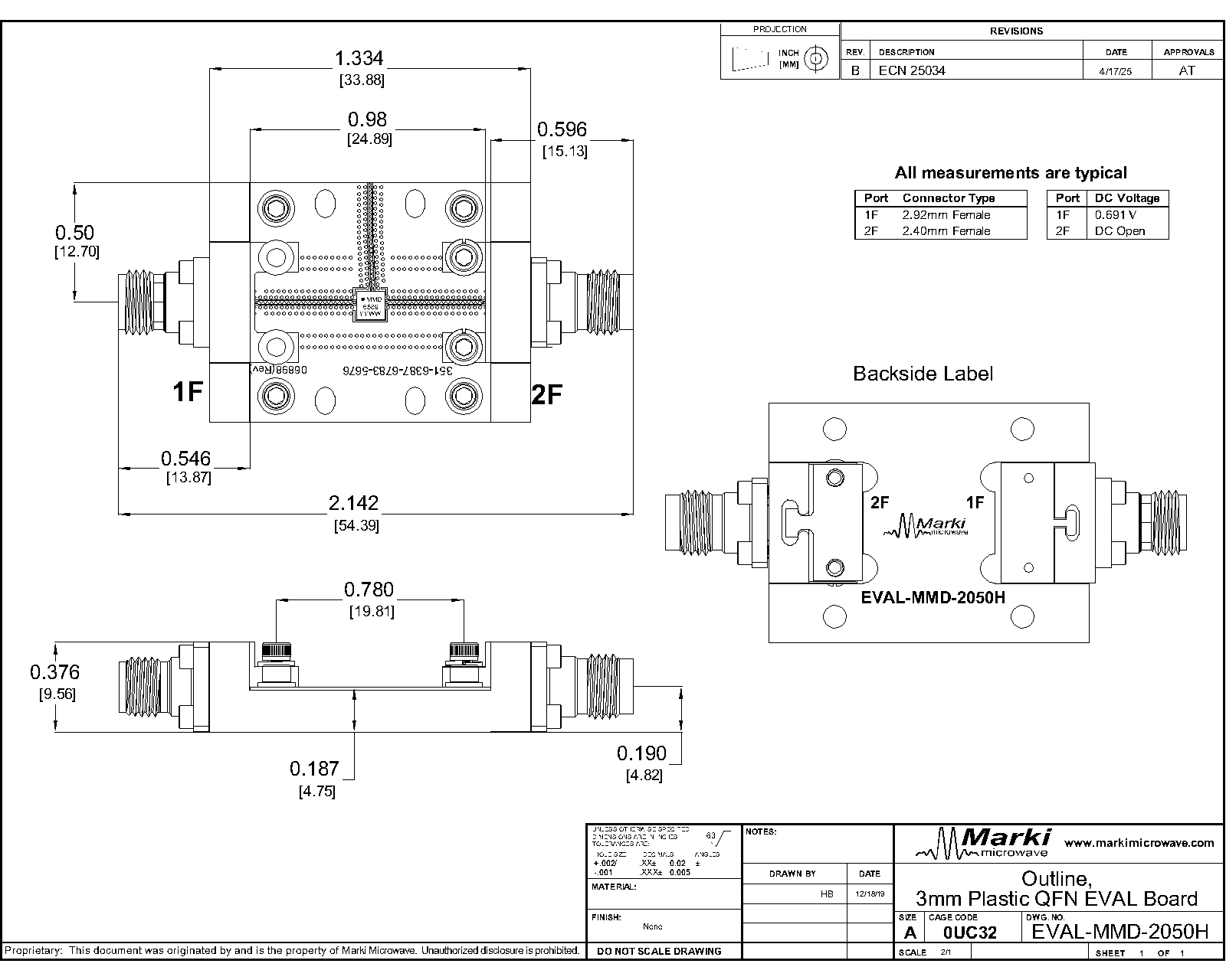
| EVAL-MMD-2050H | Evaluation Board, GaAs MMIC 20 - 50 GHz Millimeter Wave Doubler | EVAL | REACH RoHS | Released | EAR99 |
| Part Number | Description | Package | Green Status | Product Lifecycle | Export Classification |
|---|---|---|---|---|---|
| MMD-2050HSM | GaAs MMIC Millimeter Wave Doubler | QFN | REACH RoHS | Released | EAR99 |
| EVAL-MMD-2050H | Evaluation Board, GaAs MMIC 20 - 50 GHz Millimeter Wave Doubler | EVAL | REACH RoHS | Released | EAR99 |
MMD-2050HSM
GaAs MMIC Millimeter Wave Doubler
| Revision Code | Revision Date | Comment |
|---|---|---|
| - | 2020-02-01 | Initial Release |
MMD-2050HSM
GaAs MMIC Millimeter Wave Doubler
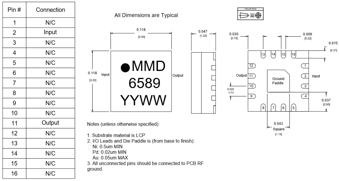
| Port | Function | Description | DC Equivalent Circuit |
|---|---|---|---|
| GND | Ground | SM package ground path is provided through the ground paddle. |  |
| Pin 11 | 2F Output | 2x Input Frequency output port. Pin 11 is DC open and AC matched to 50 Ohms from 20-50GHz |  |
| Pin 2 | 1F Input | Input 1x Frequency Port. Pin 2 is diode coupled and AC matched to 50 Ohms from 10-25GHz |  |
MMD-2050HSM
GaAs MMIC Millimeter Wave Doubler
| Parameter | Maximum Rating | Unit |
|---|---|---|
| Maximum Operating Temperature | 100 | °C |
| Maximum Storage Temperature | 125 | °C |
| Minimum Operating Temperature | -55 | °C |
| Minimum Storage Temperature | -65 | °C |
| RF Maximum Power | 29 | dBm |
| Parameter | Details | Rating |
|---|---|---|
| ESD | 250 to < 500 Volts | HBM Class 1A |
| Dimensions | - | 3 x 3 mm |
| Moisture Sensitivity Level | - | MSL 1 |
MMD-2050HSM
GaAs MMIC Millimeter Wave Doubler
| Parameter | Test Conditions | Minimum Frequency (GHz) | Maximum Frequency (GHz) | Min | Typ | Max | Unit |
|---|---|---|---|---|---|---|---|
| Conversion Loss | Second Harmonic Output | 10 | 25 | - | 12.5 | 16 | dB |
| Input Frequency Range | - | - | - | 10 | - | 25 | GHz |
| Input Power | - | - | - | 10 | - | 15 | dBm |
| Isolation, 1F 1 | Input=10-25 GHz Output=10-25 GHz | 10 | 25 | 40 | 45 | - | dB |
| Isolation, 3F 2 | Input=10–17 GHz Output=30-51 GHz | 30 | 51 | 42 | 53 | - | dB |
| Isolation, 4F 3 | Input=10–12.5 GHz Output=40-50 GHz | 40 | 50 | 22 | 24.5 | - | dB |
| Output Frequency Range | - | - | - | 20 | - | 50 | GHz |
| Suppression, 1F 4 | Input=10–25 GHz Output=10-25 GHz | 10 | 25 | 25 | 33 | - | dBc |
| Suppression, 3F 5 | Input=10–17 GHz Output=30-51 GHz | 30 | 51 | 30 | 40 | - | dBc |
| Suppression, 4F 6 | Input=10–12.5 GHz Output=40-50 GHz | 40 | 50 | 8 | 10.5 | - | dBc |
[1][2][3] Isolation is defined as the harmonic power relative to the 1F fundamental input power.
[4][5][6] Suppressions and isolations measured with an input source with >60dBc (relative to fundamental input) harmonic suppression. Suppression is defined as the harmonic power relative to the 2F doubled output power.
MMD-2050HSM
GaAs MMIC Millimeter Wave Doubler


MMD-2050HSM
GaAs MMIC Millimeter Wave Doubler


MMD-2050HSM
GaAs MMIC Millimeter Wave Doubler
MMD-2050HSM
GaAs MMIC Millimeter Wave Doubler
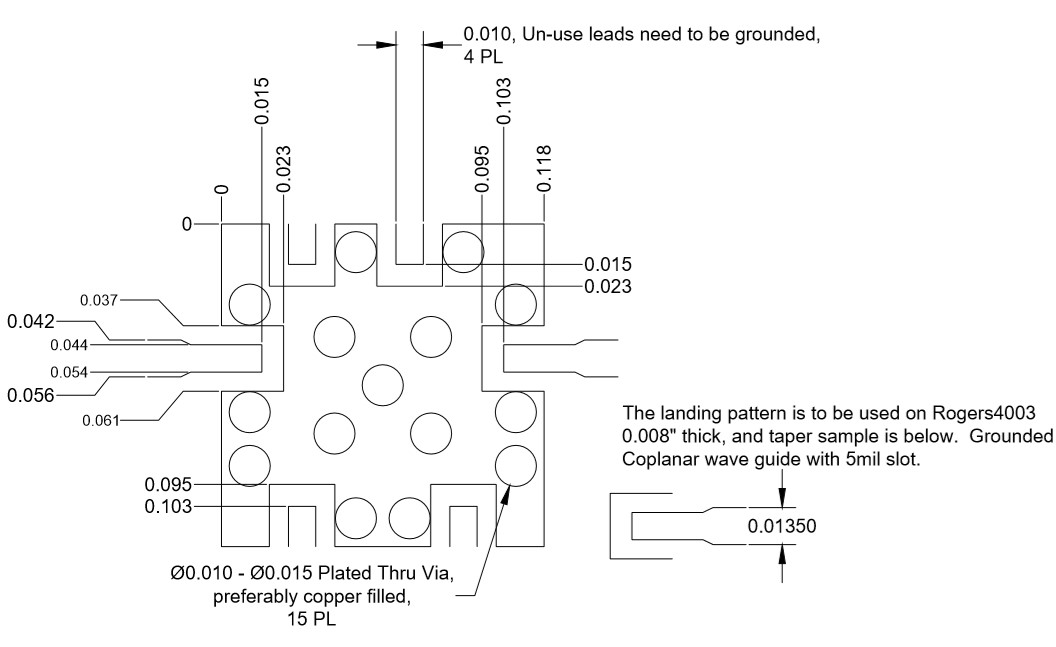
Download : Footprint Drawing
MMD-2050HSM
GaAs MMIC Millimeter Wave Doubler