Port Diagram
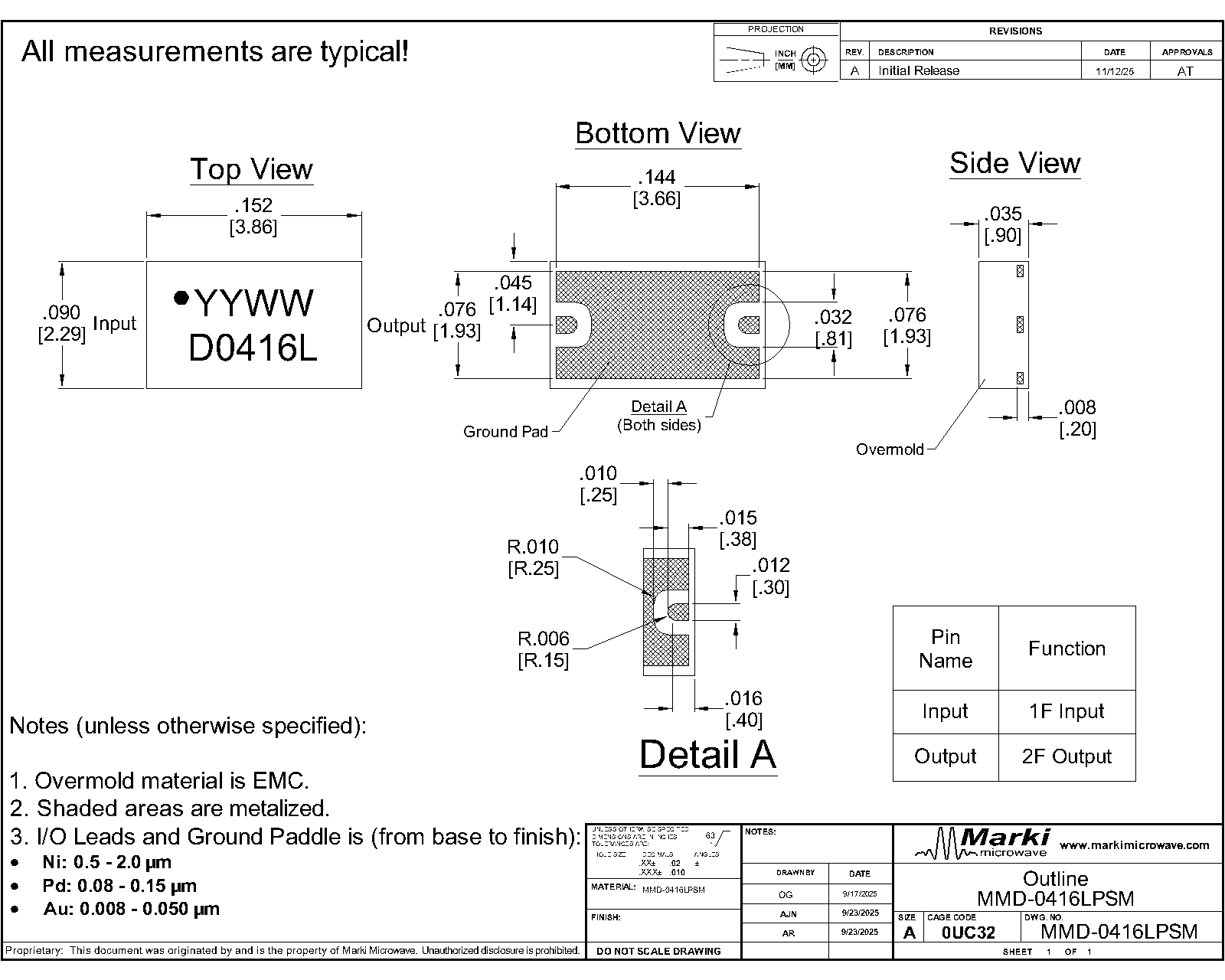
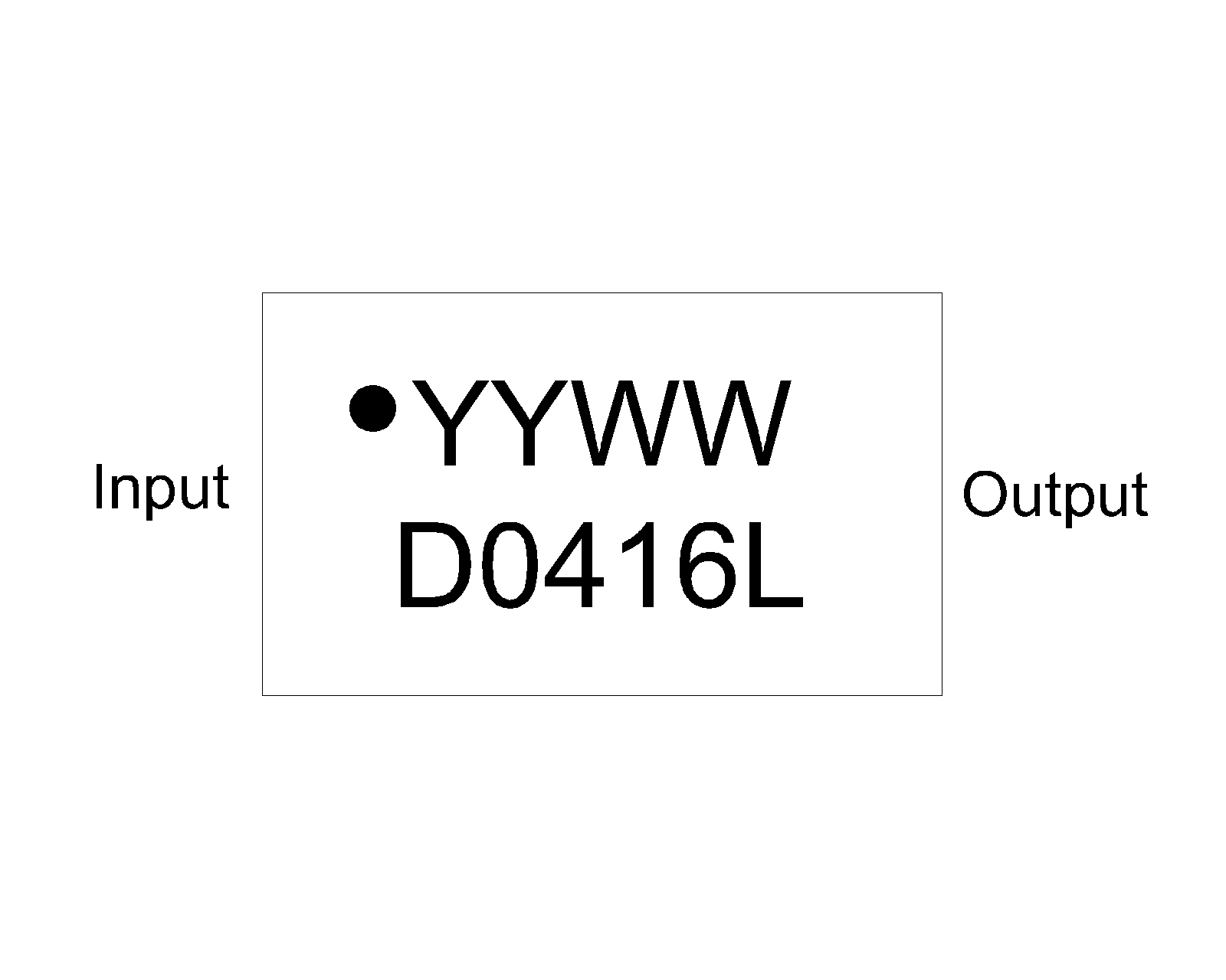
A top-down x-ray view of the MMD-0416LPSM’s PSM package outline drawing is shown below. The MMD-0416LPSM should only be used in the forward direction, with the input and output ports given in Port Functions.

Sales: 408-778-9952 | General: 408-778-4200 | Fax: 408-778-4300
Sales & Customer Support: [email protected]
Tech Support: [email protected]
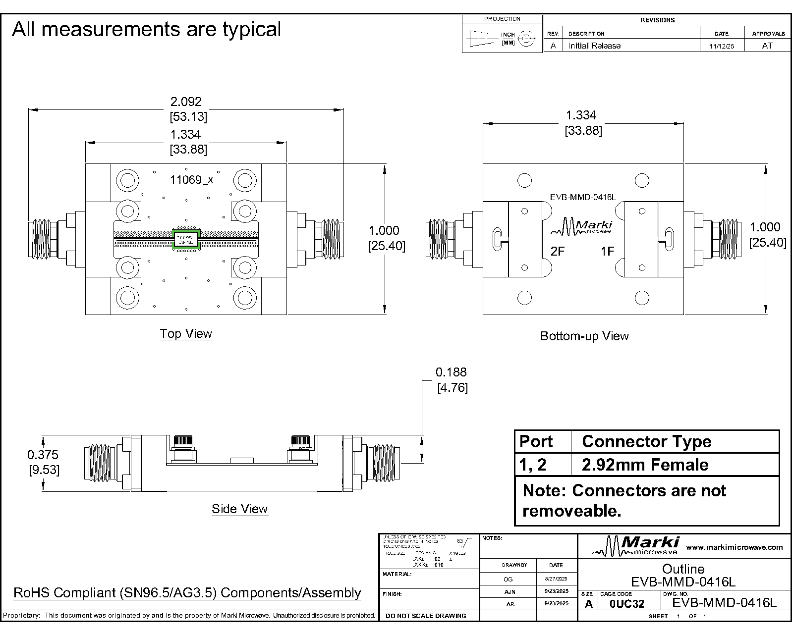
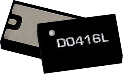
The MMD-0416LPSM is a GaAs Schottky-diode MMIC frequency doubler operating with an input range of 2 to 8 GHz and a doubled output of 4 to 16 GHz. It delivers low conversion loss, high fundamental and LO isolation, and strong harmonic suppression across a wide bandwidth. The MMD-0416LPSM is available in a compact 2.29 x 3.86mm DFN package for easy SMT integration, as well as a connectorized evaluation board.

| Part Number | Description | Package | Green Status | Product Lifecycle | Export Classification |
|---|---|---|---|---|---|
| MMD-0416LPSM | GaAs MMIC Doubler | DFN | REACH RoHS | Released | EAR99 |
| EVB-MMD-0416L | Evaluation Board, GaAs MMIC 4 - 16 GHz Doubler | EVB | REACH RoHS | Released | EAR99 |
| Part Number | Description | Package | Green Status | Product Lifecycle | Export Classification |
|---|---|---|---|---|---|
| MMD-0416LPSM | GaAs MMIC Doubler | DFN | REACH RoHS | Released | EAR99 |
| EVB-MMD-0416L | Evaluation Board, GaAs MMIC 4 - 16 GHz Doubler | EVB | REACH RoHS | Released | EAR99 |
MMD-0416LPSM
GaAs MMIC Doubler
| Revision Code | Revision Date | Comment |
|---|---|---|
| - | 2025-12-10 | Initial Release |
| A | 2025-12-17 | 3D Models Updated. |
MMD-0416LPSM
GaAs MMIC Doubler
A top-down x-ray view of the MMD-0416LPSM’s PSM package outline drawing is shown below. The MMD-0416LPSM should only be used in the forward direction, with the input and output ports given in Port Functions.
| Port | Function | Description | DC Equivalent Circuit |
|---|---|---|---|
| GND | Ground | PSM package ground path is provided through the ground paddle. |  |
| Input | 1F Input | Input 1x Frequency input port. This pin is DC open for the PSM package. | 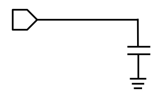 |
| Output | 2F Output | Output 2x Frequency output port. This pin is DC open for the PSM package. | |
MMD-0416LPSM
GaAs MMIC Doubler
The Absolute Maximum Ratings indicate limits beyond which damage may occur to the device. All Absolute Maximum Ratings are individual and should not be met in parallel. If these limits are exceeded or multiple are met in parallel the device may be inoperable or have a reduced lifetime.
| Parameter | Maximum Rating | Unit |
|---|---|---|
| Maximum Operating Temperature | 100 | °C |
| Maximum Storage Temperature | 125 | °C |
| Minimum Operating Temperature | -55 | °C |
| Minimum Storage Temperature | -65 | °C |
| Power Handling, at any Port (25°C) | 27 | dBm |
| Parameter | Details | Rating |
|---|---|---|
| ESD | 250 to < 500 Volts | HBM Class 1A |
| Dimensions | - | 2.29 x 3.86 mm |
| Moisture Sensitivity Level | - | MSL 1 |
The Recommended Operating Conditions indicate the limits, inside which the device should be operated, to guarantee the performance given in Electrical Specifications Operating outside these limits may not necessarily cause damage to the device, but the performance may degrade outside the limits of the electrical specifications. For limits, above which damage may occur, see Absolute Maximum Ratings.
| Parameter | Min | Nominal | Max | Unit |
|---|---|---|---|---|
| Ambient Temperature | -55 | 25 | 100 | °C |
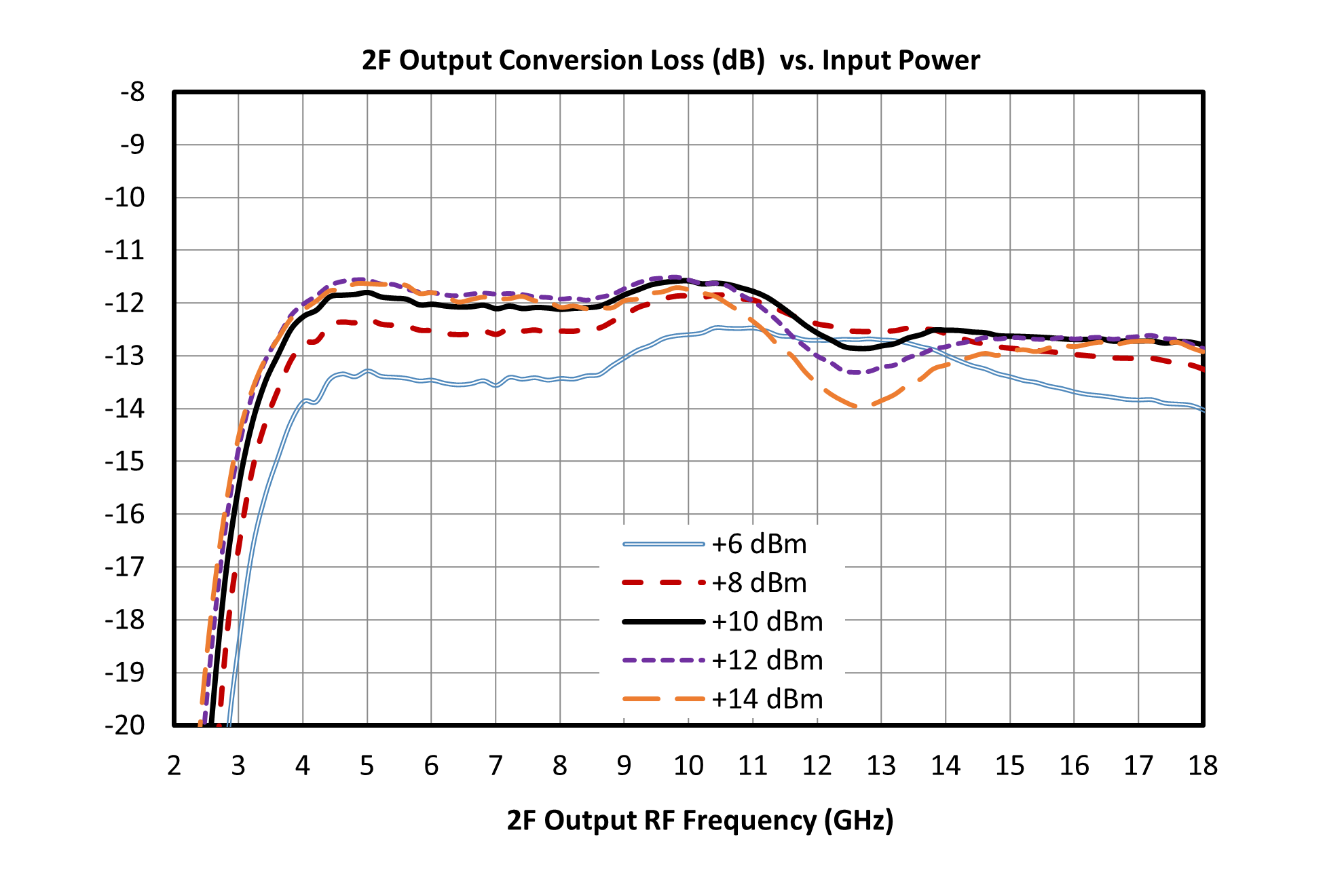
| Input Power | 6 | 10 | 14 | dBm |
MMD-0416LPSM
GaAs MMIC Doubler
The electrical specifications apply at TA=+25°C in a 50Ω system. Typical data shown is for the connectorized EVB package doubler used in the forward direction with a +10 dBm sine wave input. Min and Max limits apply only to our connectorized units and are guaranteed at TA=+25°C.
| Parameter | Test Conditions | Minimum Frequency (GHz) | Maximum Frequency (GHz) | Min | Typ | Max | Unit |
|---|---|---|---|---|---|---|---|
| Input Frequency Range | - | - | - | 2 | - | 8 | GHz |
| Output Frequency Range | - | - | - | 4 | - | 16 | GHz |
| Input Power | - | - | - | 6 | 10 | 14 | dBm |
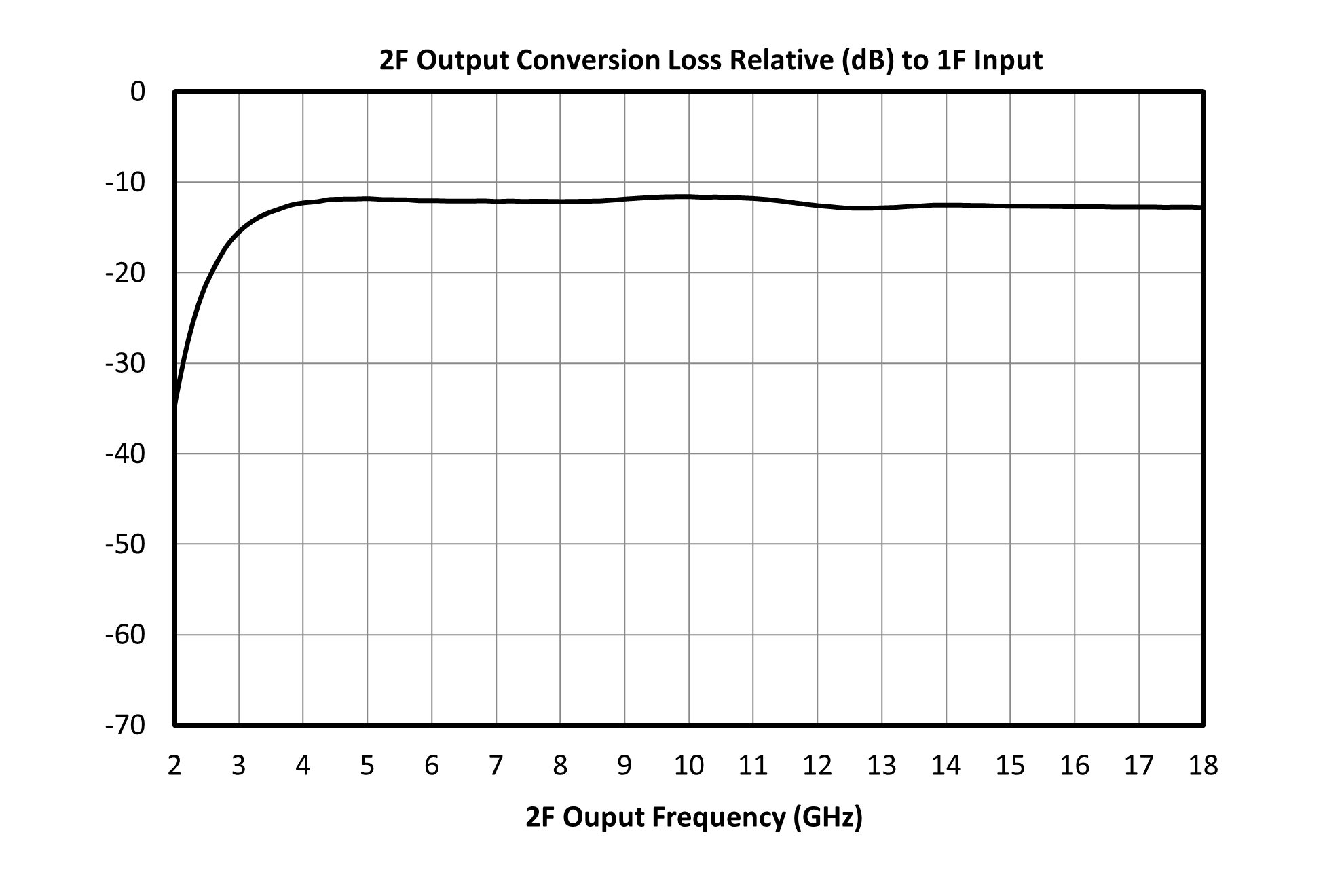
| Conversion Loss 1 | Second Harmonic Output | 4 | 16 | - | 12 | - | dB |
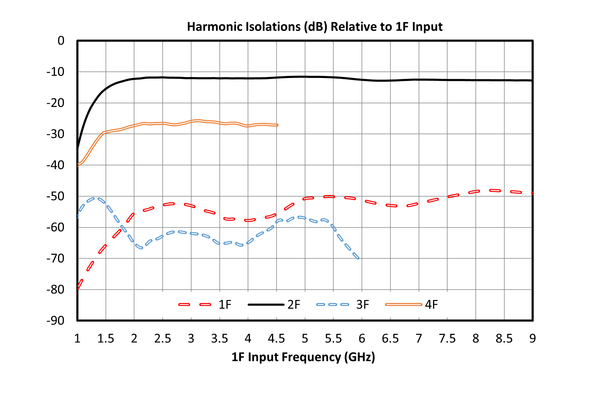
| Isolation, 3F 2 | Input = 2 – 5.33 GHz Output = 6 - 16 GHz | 6 | 16 | - | 62 | - | dB |
| Isolation, 4F 3 | Input = 2 – 4 GHz Output = 8 - 16 GHz | 8 | 16 | - | 27 | - | dB |
| Isolation, 1F 4 | Input = 2 – 8 GHz Output = 2 – 8 GHz | 2 | 8 | - | 50 | - | dB |
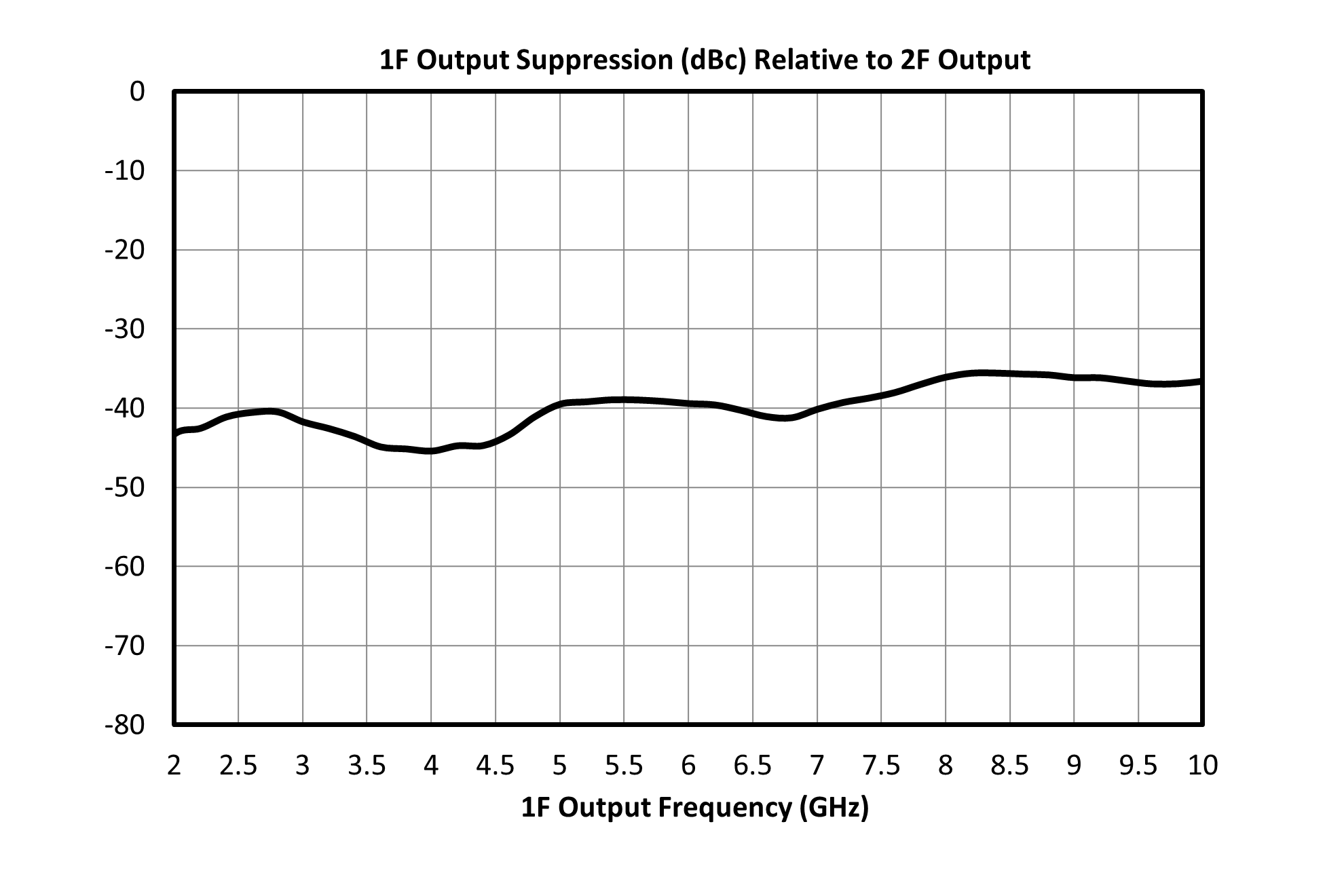
| Suppression, 1F 5 | Input = 2 – 8 GHz Output = 2 – 8 GHz | 2 | 8 | - | 37 | - | dBc |
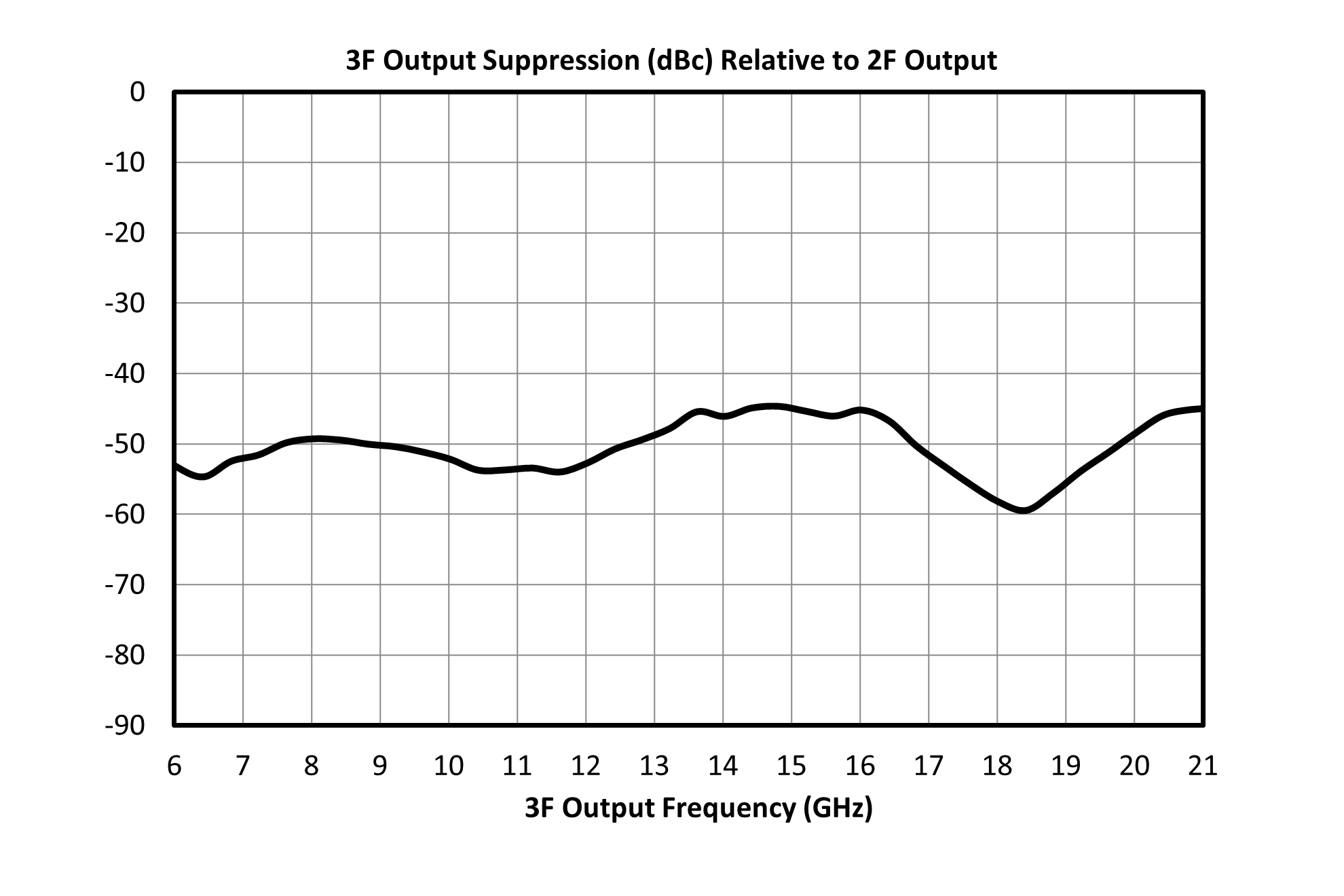
| Suppression, 3F 6 | Input = 2 – 5.33 GHz Output = 6 - 16 GHz | 6 | 16 | - | 50 | - | dBc |
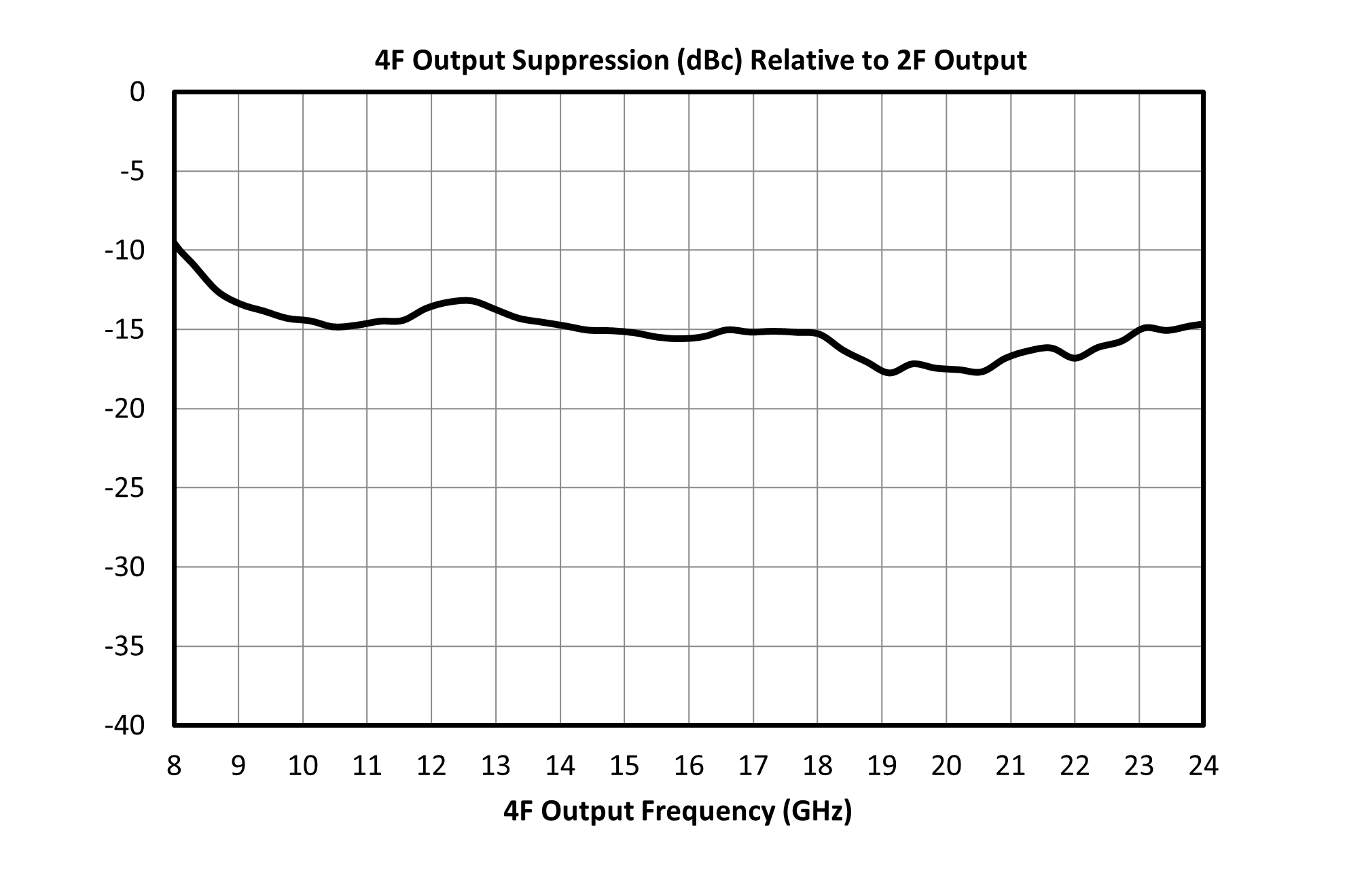
| Suppression, 4F 7 | Input = 2 – 4 GHz Output = 8 - 16 GHz | 8 | 16 | - | 14 | - | dBc |
| Parameter | Test Conditions | Minimum Frequency (GHz) | Maximum Frequency (GHz) | Min | Typ | Max | Unit |
|---|---|---|---|---|---|---|---|
| Input Frequency Range | - | - | - | 2 | - | 8 | GHz |
| Output Frequency Range | - | - | - | 4 | - | 16 | GHz |
| Input Power | - | - | - | 6 | 10 | 14 | dBm |
| Conversion Loss 1 | Second Harmonic Output | 4 | 16 | - | 12 | - | dB |
| Isolation, 3F 2 | Input = 2 – 5.33 GHz Output = 6 - 16 GHz | 6 | 16 | - | 62 | - | dB |
| Isolation, 4F 3 | Input = 2 – 4 GHz Output = 8 - 16 GHz | 8 | 16 | - | 27 | - | dB |
| Isolation, 1F 4 | Input = 2 – 8 GHz Output = 2 – 8 GHz | 2 | 8 | - | 50 | - | dB |
| Suppression, 1F 5 | Input = 2 – 8 GHz Output = 2 – 8 GHz | 2 | 8 | - | 37 | - | dBc |
| Suppression, 3F 6 | Input = 2 – 5.33 GHz Output = 6 - 16 GHz | 6 | 16 | - | 50 | - | dBc |
| Suppression, 4F 7 | Input = 2 – 4 GHz Output = 8 - 16 GHz | 8 | 16 | - | 14 | - | dBc |
[1] with +10 dBm RF Input
[2][3][4] Isolation is defined as the harmonic power relative to the 1F fundamental input power.
[5][6][7] Suppressions and isolations measured with an input source with >60dBc (relative to fundamental input) harmonic suppression. Suppression is defined as the harmonic power relative to the 2F doubled output power.
MMD-0416LPSM
GaAs MMIC Doubler
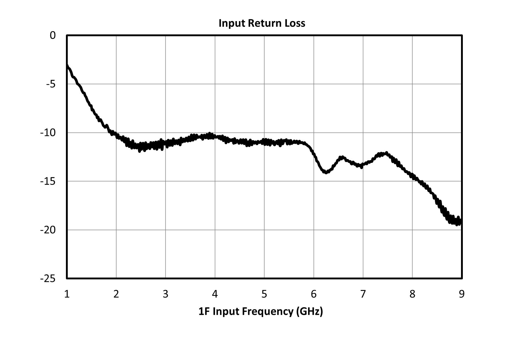
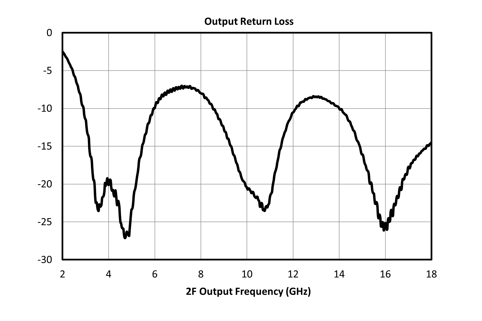
The EVB trace losses are de-embedded for the metrics has shown here.
MMD-0416LPSM
GaAs MMIC Doubler
MMD-0416LPSM
GaAs MMIC Doubler
MMD-0416LPSM
GaAs MMIC Doubler
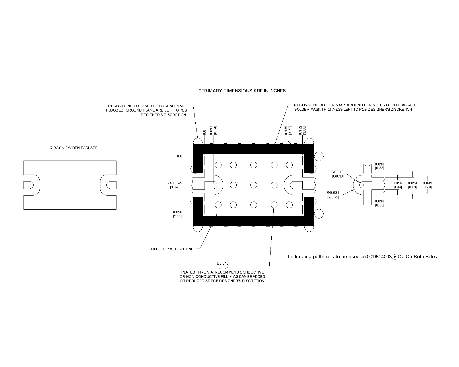
Download : Footprint Drawing
MMD-0416LPSM
GaAs MMIC Doubler