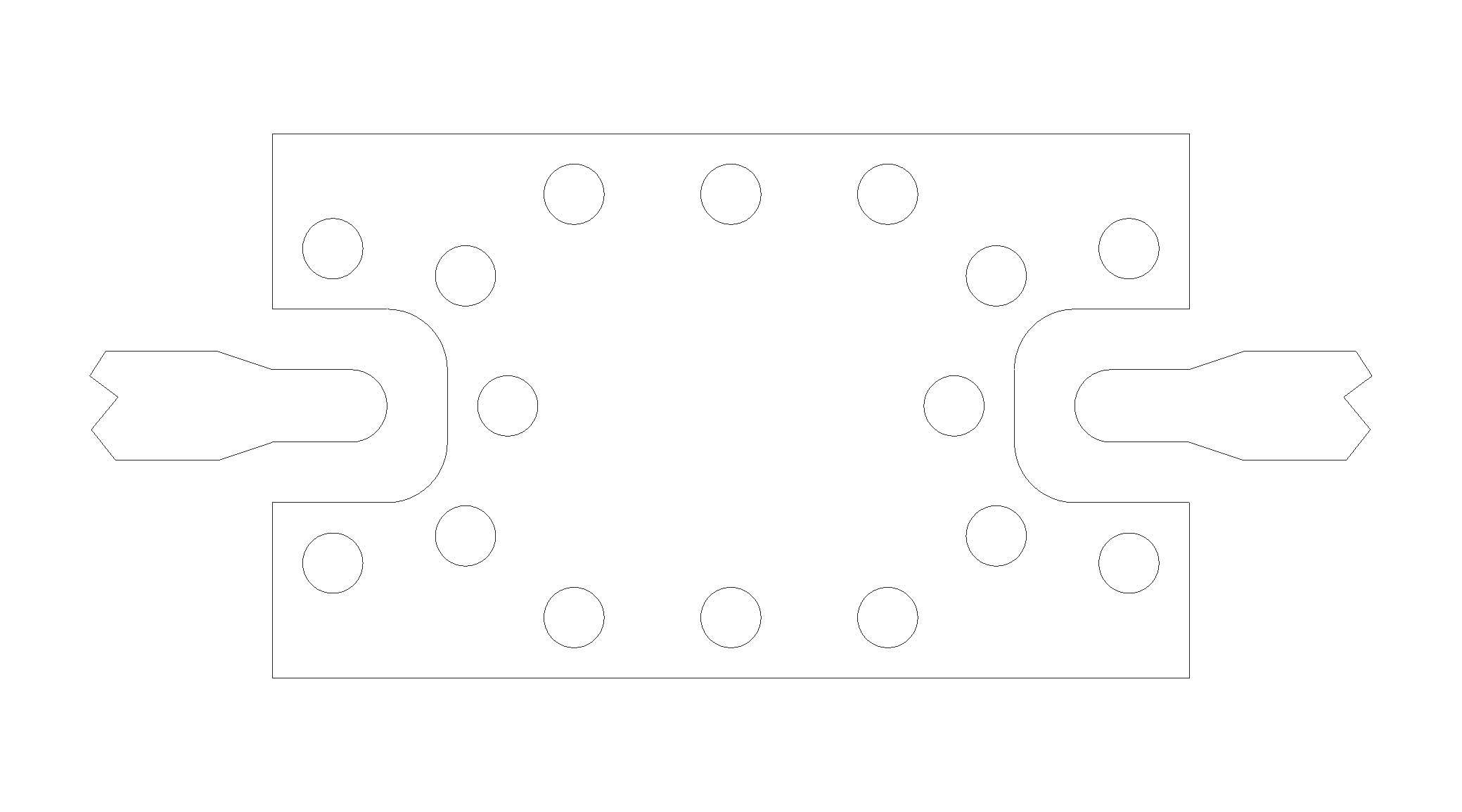
Port Diagram

END OF LIFE

Sales: 408-778-9952 | General: 408-778-4200 | Fax: 408-778-4300
Sales & Customer Support: [email protected]
Tech Support: [email protected]
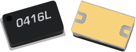
The MLD-0416SM is a Surface Mount Microlithic™ doubler. As with all Microlithic™ devices, it features excellent conversion loss and harmonic suppressions across a broad bandwidth and in a miniaturized form factor. Accurate, nonlinear software models are available for Microwave Office through the Marki Microwave PDK. The MLD-0416SM is a lead free, RoHS compliant package compatible with standard leaded and lead-free solder reflows. The MLD-0416SM is an excellent alternative to Marki Microwave doublers packaged in surface mount packages such as the EZ carrier.
N/A

| Part Number | Description | Package | Green Status | Product Lifecycle | Export Classification | Recommended Replacement |
|---|---|---|---|---|---|---|
| MLD-0416LSM | MICROLITHIC™ DOUBLER | SM | REACH RoHS | End of Life | EAR99 | MMD-0415HPSM |
| EVAL-MLD-0416L | Evaluation Board, Microlithic Doubler 4 -16 GHz | EVAL | REACH RoHS | Obsolete | EAR99 | - |
| Part Number | Description | Package | Green Status | Product Lifecycle | Export Classification | Recommended Replacement |
|---|---|---|---|---|---|---|
| MLD-0416LSM | MICROLITHIC™ DOUBLER | SM | REACH RoHS | End of Life | EAR99 | MMD-0415HPSM |
| EVAL-MLD-0416L | Evaluation Board, Microlithic Doubler 4 -16 GHz | EVAL | REACH RoHS | Obsolete | EAR99 | - |
MLD-0416LSM
MICROLITHIC™ DOUBLER
| Revision Code | Revision Date | Comment |
|---|---|---|
| - | 2024-07-31 | Product Lifecycle Update to EOL |
MLD-0416LSM
MICROLITHIC™ DOUBLER
| Port | Function | Description | DC Equivalent Circuit |
|---|---|---|---|
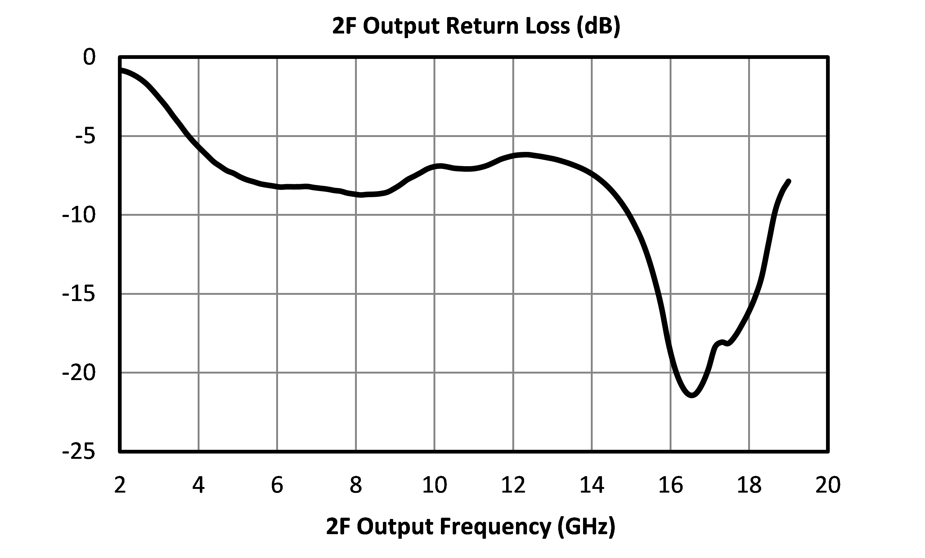
| 2F | 2F Output | The output port is DC short to ground and AC matched to 50 Ohms from 4 to 16 GHz. Blocking capacitor is optional. |  |
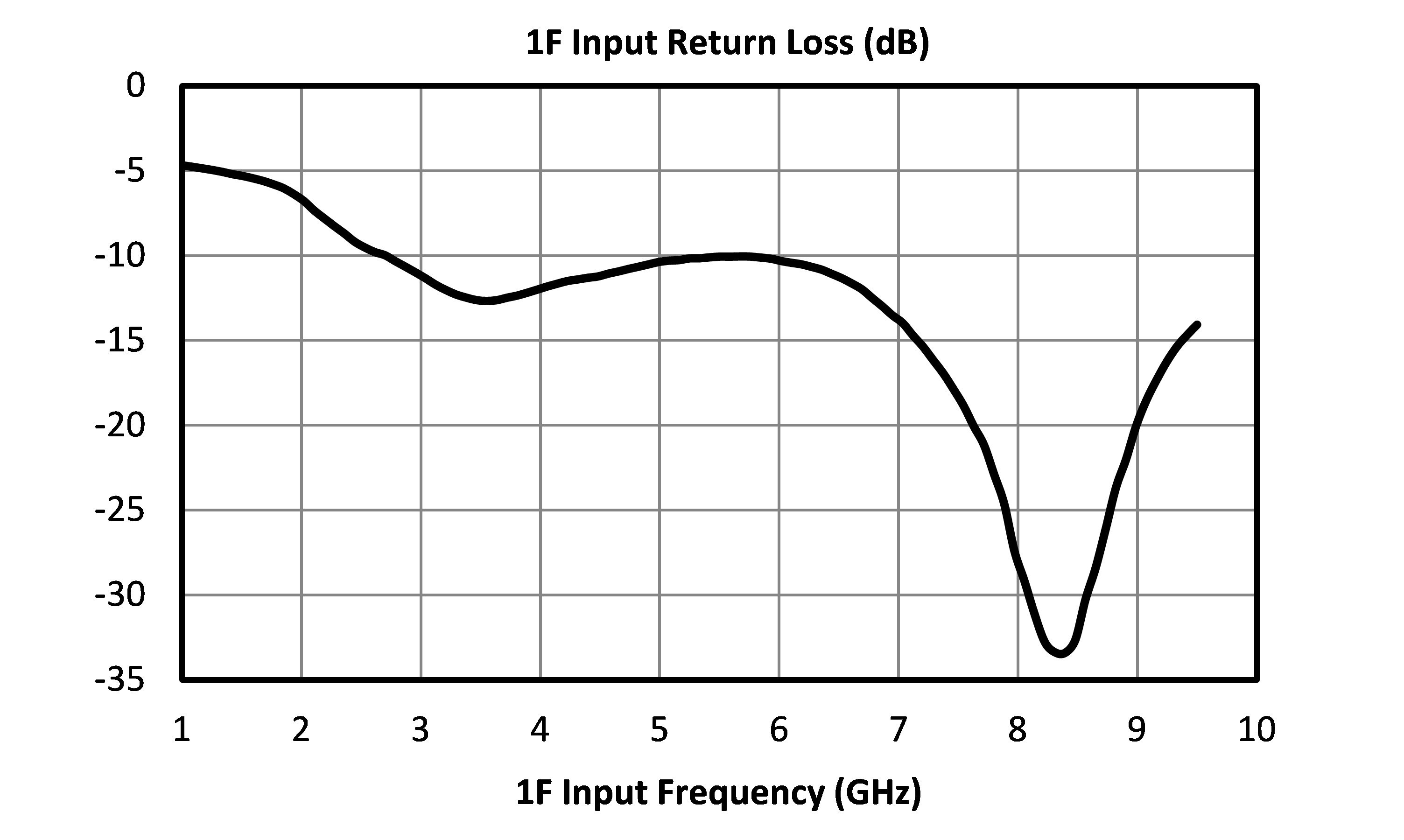
| F | F input | The input port is DC short to ground and AC matched to 50 Ohms from 2 to 8 GHz. Blocking capacitor is optional. | |
| GND | Ground | Ground is provided through substrate ground paddle. |  |
MLD-0416LSM
MICROLITHIC™ DOUBLER
The Absolute Maximum Ratings indicate limits beyond which damage may occur to the device. If these limits are exceeded, the device may be inoperable or have a reduced lifetime.
| Parameter | Maximum Rating | Unit |
|---|---|---|
| DC Current | 1 | A |
| Maximum Operating Temperature | 100 | °C |
| Maximum Storage Temperature | 125 | °C |
| Minimum Operating Temperature | -55 | °C |
| Minimum Storage Temperature | -65 | °C |
| RF Power Handling, 100°C | 20 | dBm |
| RF Power Handling, 25°C | 25 | dBm |
| Parameter | Details | Rating |
|---|---|---|
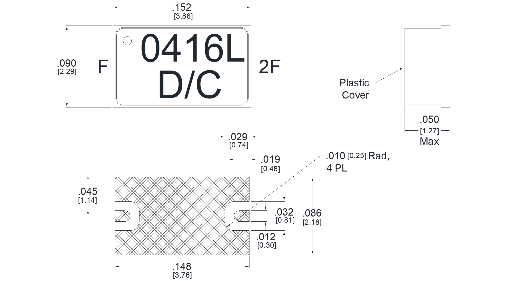
| Dimensions | - | 3.86x2.29mm |
| Moisture Sensitivity Level | - | MSL 1 |
MLD-0416LSM
MICROLITHIC™ DOUBLER
Specifications guaranteed from -55 to +100C, measured in a 50Ω system.
| Parameter | Test Conditions | Minimum Frequency (GHz) | Maximum Frequency (GHz) | Min | Typ | Max | Unit |
|---|---|---|---|---|---|---|---|
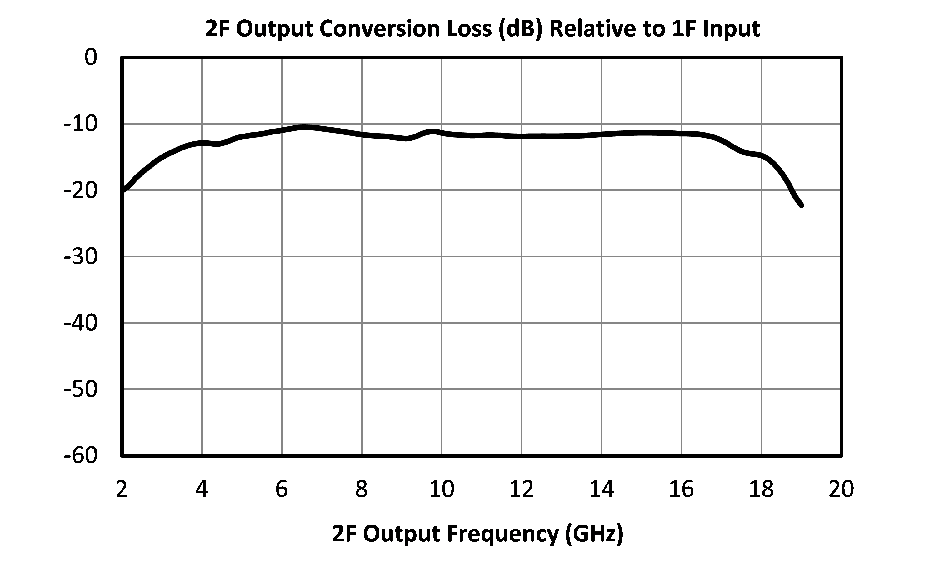
| Conversion Loss | Second Harmonic Output | - | - | - | 12 | 17 | dB |
| Input Frequency Range | - | - | - | 2 | - | 8 | GHz |
| Input Power 1 | - | - | - | 6 | - | 14 | dBm |
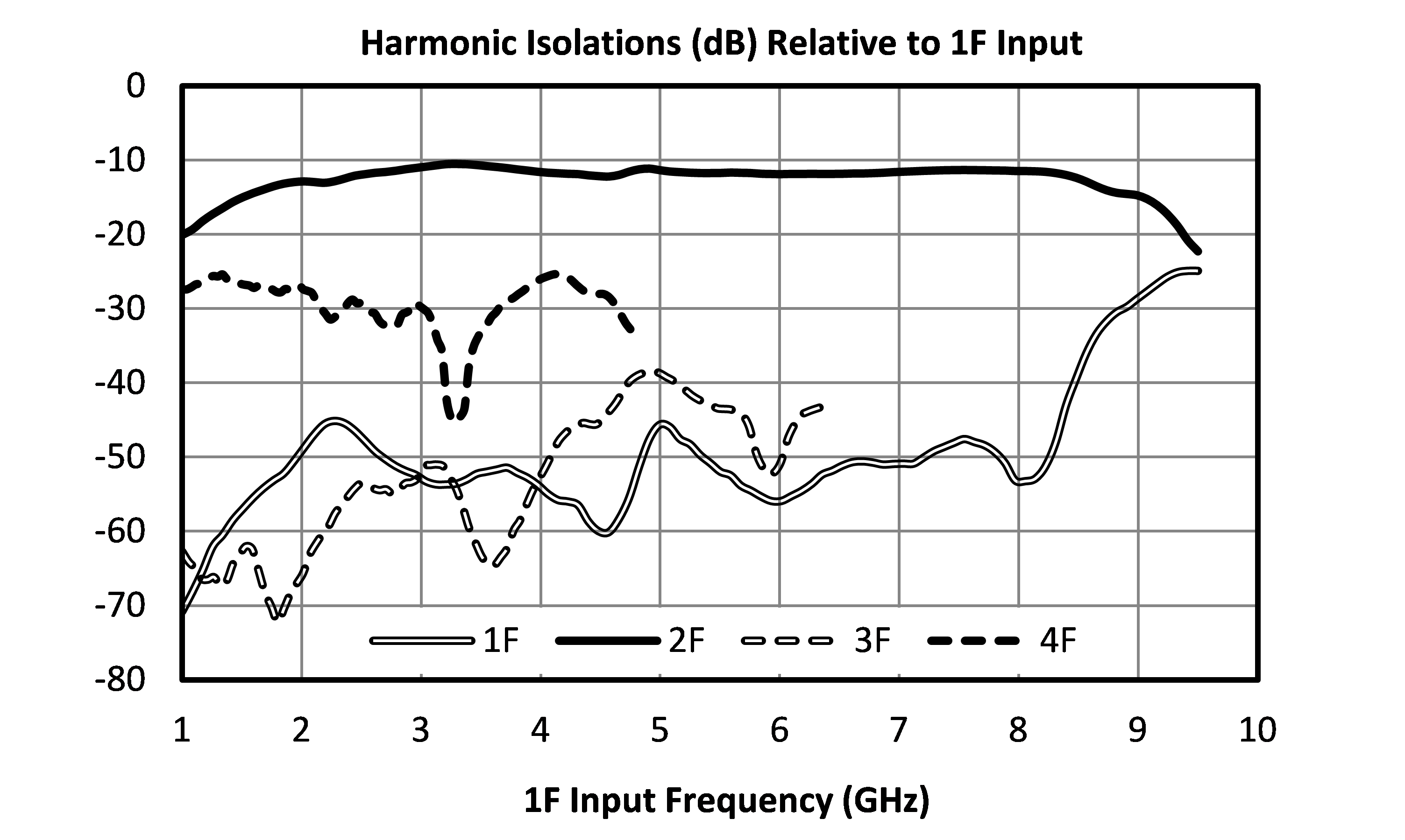
| Isolation, 1F | - | - | - | - | 52 | - | dB |
| Isolation, 3F | - | - | - | - | 52 | - | dB |
| Isolation, 4F | - | - | - | - | 32 | - | dB |
| Output Frequency Range | - | - | - | 4 | - | 16 | GHz |
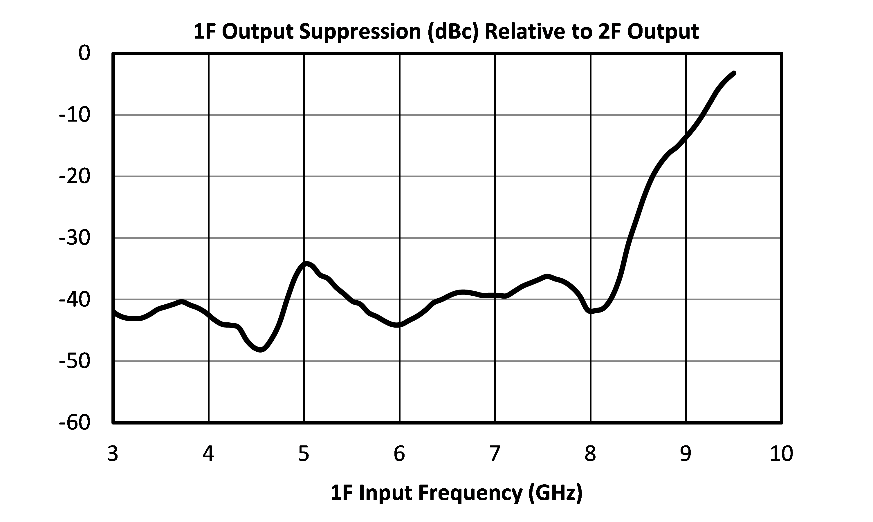
| Suppression, 1F | - | - | - | - | 40 | - | dB |
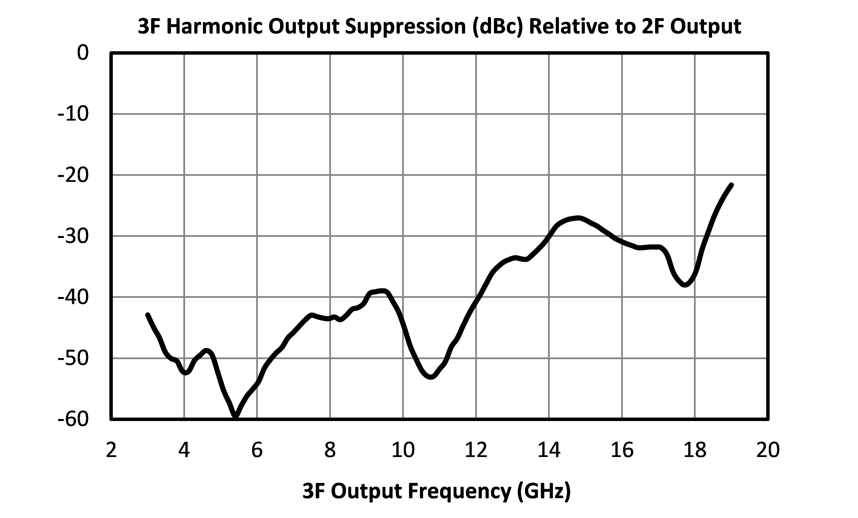
| Suppression, 3F | - | - | - | - | 40 | - | dB |
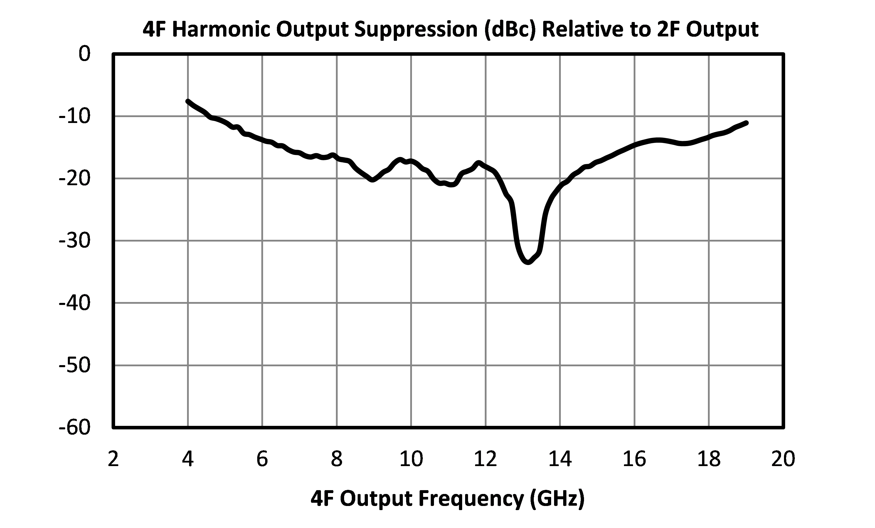
| Suppression, 4F | - | - | - | - | 20 | - | dB |
| Parameter | Test Conditions | Minimum Frequency (GHz) | Maximum Frequency (GHz) | Min | Typ | Max | Unit |
|---|---|---|---|---|---|---|---|
| Conversion Loss | Second Harmonic Output | - | - | - | 12 | 17 | dB |
| Input Frequency Range | - | - | - | 2 | - | 8 | GHz |
| Input Power 1 | - | - | - | 6 | - | 14 | dBm |
| Isolation, 1F | - | - | - | - | 52 | - | dB |
| Isolation, 3F | - | - | - | - | 52 | - | dB |
| Isolation, 4F | - | - | - | - | 32 | - | dB |
| Output Frequency Range | - | - | - | 4 | - | 16 | GHz |
| Suppression, 1F | - | - | - | - | 40 | - | dB |
| Suppression, 3F | - | - | - | - | 40 | - | dB |
| Suppression, 4F | - | - | - | - | 20 | - | dB |
[1] L-Version
Suppression is relative to doubled output power. Isolation is defined as relative to the fundamental input power. For higher input power, alternative diode options may be available. Contact factory.
MLD-0416LSM
MICROLITHIC™ DOUBLER
MLD-0416LSM
MICROLITHIC™ DOUBLER
MLD-0416LSM
MICROLITHIC™ DOUBLER
Download : Footprint Drawing