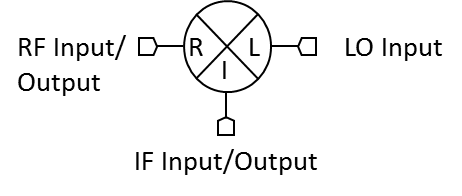
Port Diagram
Sales: 408-778-9952 | General: 408-778-4200 | Fax: 408-778-4300
Sales & Customer Support: [email protected]
Tech Support: [email protected]
The MT3-0113HCQG is a triple balanced passive diode GaAs MMIC mixer offering high dynamic range, low conversion loss, and excellent repeatability. As with all T3 mixers, this mixer offers unparalleled nonlinear performance in terms of IIP3, P1dB, and spurious performance with a flexible LO drive requirement from +16 dBm to +24 dBm. The MT3-0113HCQG is available in a surface-mount outline, or in an SMA connectorized evaluation fixture. The MT3-0113HCQG is a superior alternative to Marki Microwave carrier and packaged T3 mixers, and is form-fit compatible with legacy T3’s in the CQ and CQG footprints.
N/A
| Part Number | Description | Package | Green Status | Product Lifecycle | Export Classification |
|---|---|---|---|---|---|
| MT3-0113HCQG-2 | GaAs MMIC High Dynamic Range Mixer | CQG | REACH RoHS | Released | EAR99 |
| MT3-0113HCQG-1 | GaAs MMIC High Dynamic Range Mixer | CQG | REACH RoHS | Released | EAR99 |
| EVAL-MT3-0113H | Evaluation Board, GaAs MMIC High Dynamic Range Mixer | EVAL | REACH RoHS | Released | EAR99 |
MT3-0113HCQG-1
GaAs MMIC High Dynamic Range Mixer
| Revision Code | Revision Date | Comment |
|---|---|---|
| - | 2018-10-01 | Pre-release |
| A | 2019-02-01 | Active - Full Production |
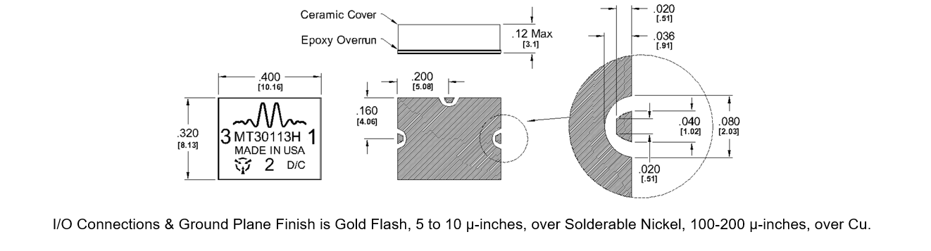
| B | 2020-05-01 | Changed cover to ceramic |
| C | 2022-02-01 | Added -1 port configuration option |
MT3-0113HCQG-1
GaAs MMIC High Dynamic Range Mixer
| Port | Function | Description | DC Equivalent Circuit |
|---|---|---|---|
| Port 1 | LO | Port 1 is DC short and AC matched to 50 Ω from 1.5 to 13 GHz. Blocking capacitor is optional. |  |
| Port 2 | IF | Port 2 is DC open. Blocking capacitor is optional. |  |
| Port 3 | RF | Port 3 is DC short and AC matched to 50 Ω from 1.5 to 13 GHz. Blocking capacitor is optional. | |
MT3-0113HCQG-1
GaAs MMIC High Dynamic Range Mixer
| Port | Function | Description | DC Equivalent Circuit |
|---|---|---|---|
| Port 1 | RF | Port 1 is DC short and AC matched to 50 Ω from 1.5 to 13 GHz. Blocking capacitor is optional. | |
| Port 2 | IF | Port 2 is DC open. Blocking capacitor is optional. | |
| Port 3 | LO | Port 3 is DC short and AC matched to 50 Ω from 1.5 to 13 GHz. Blocking capacitor is optional. | |
MT3-0113HCQG-1
GaAs MMIC High Dynamic Range Mixer
| Parameter | Maximum Rating | Unit |
|---|---|---|
| Maximum Operating Temperature | 100 | °C |
| Maximum Storage Temperature | 150 | °C |
| Minimum Operating Temperature | -40 | °C |
| Minimum Storage Temperature | -40 | °C |
| RF Power Handling (RF+LO) | 30 | dBm |
| Parameter | Details | Rating |
|---|---|---|
| Dimensions | - | 10.16 x 8.13 mm |
| Moisture Sensitivity Level | - | MSL 1 |
| Parameter | Min | Nominal | Max | Unit |
|---|---|---|---|---|
| LO Input Power | 16 | - | 24 | - |
MT3-0113HCQG-1
GaAs MMIC High Dynamic Range Mixer
Specifications guaranteed over -40 to +100°C temperature range, measured in a 50Ω system.
| Parameter | Port Configuration | Test Conditions | Min | Typ | Max | Unit |
|---|---|---|---|---|---|---|
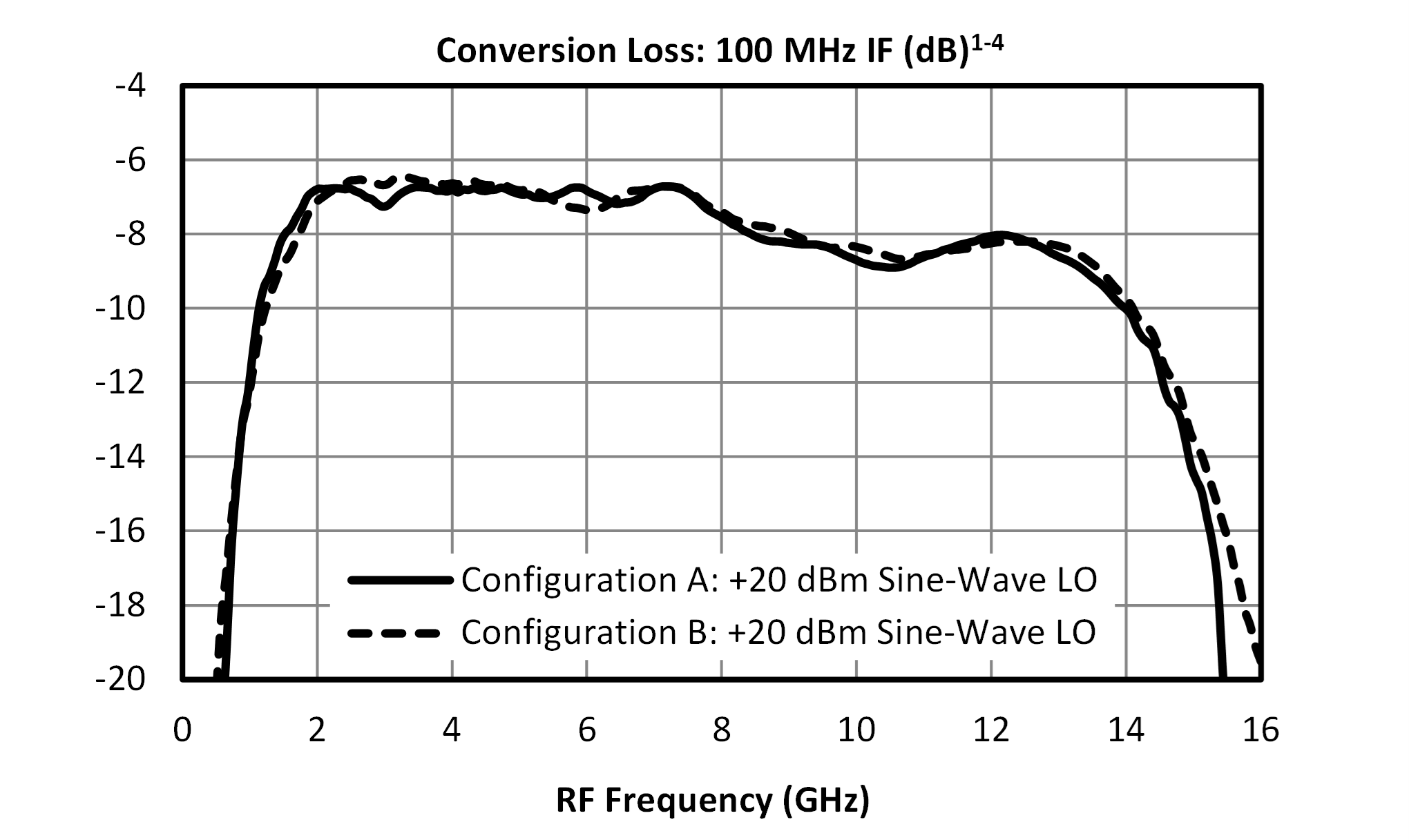
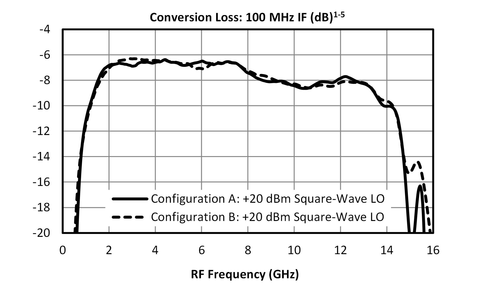
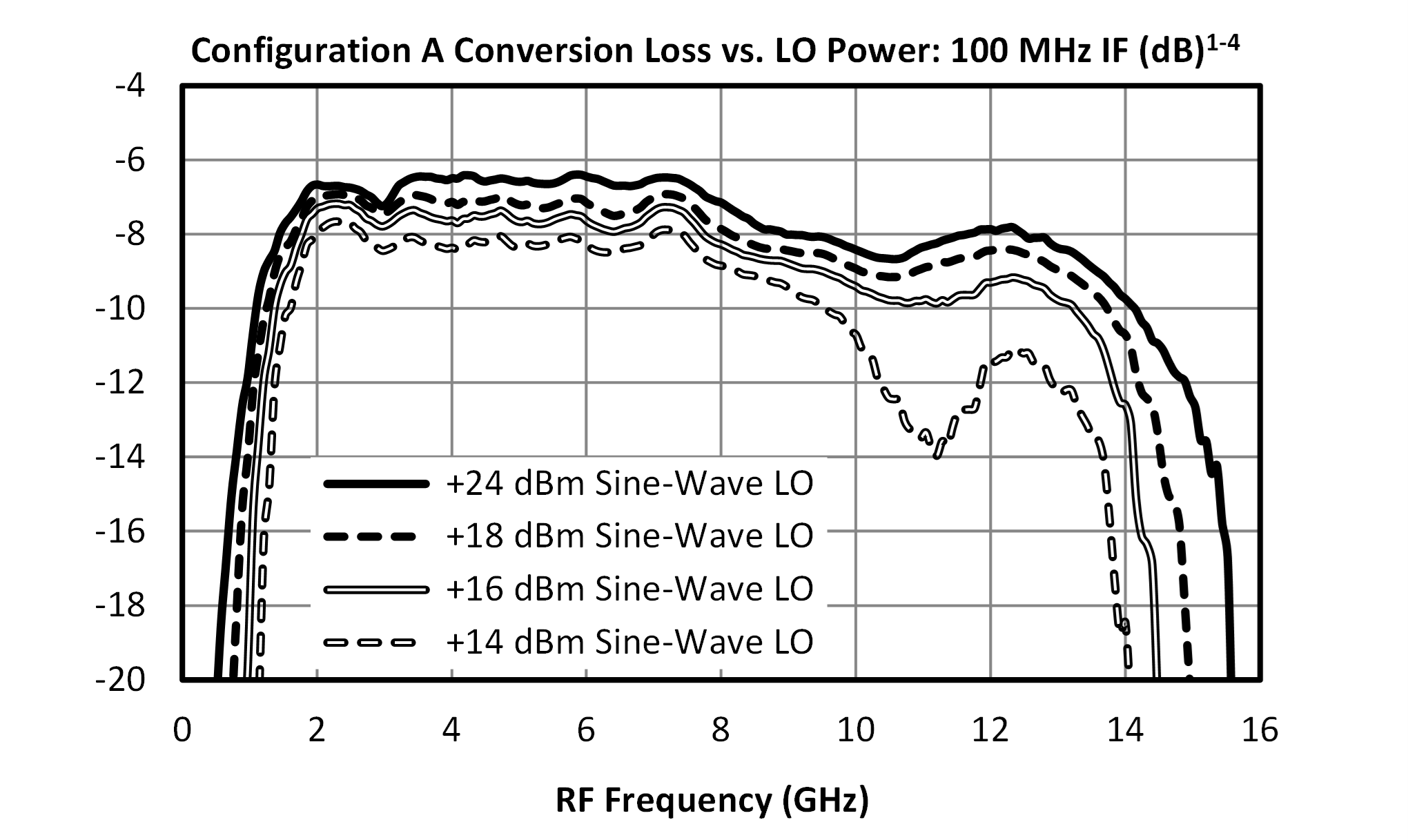
| Conversion Loss 1 | A | LO/RF=1.5-13 GHz IF=0.01-0.5 GHz LO Drive Level= 20 | - | 7.5 | 10.5 | dB |
| Conversion Loss 2 | A | LO/RF=1.5-13 GHz IF=0.5-7 GHz | - | 10 | - | dB |
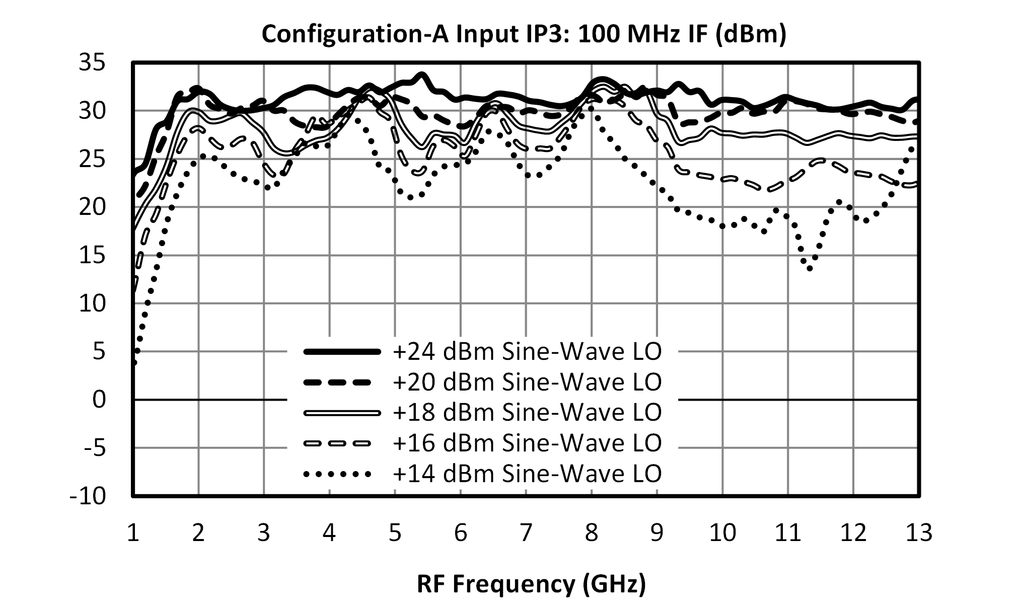
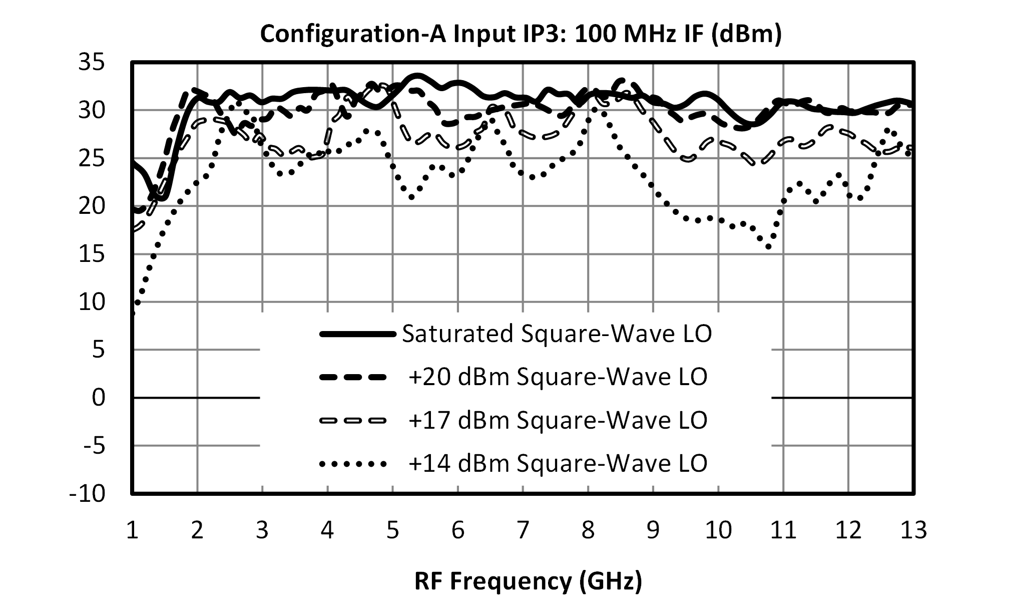
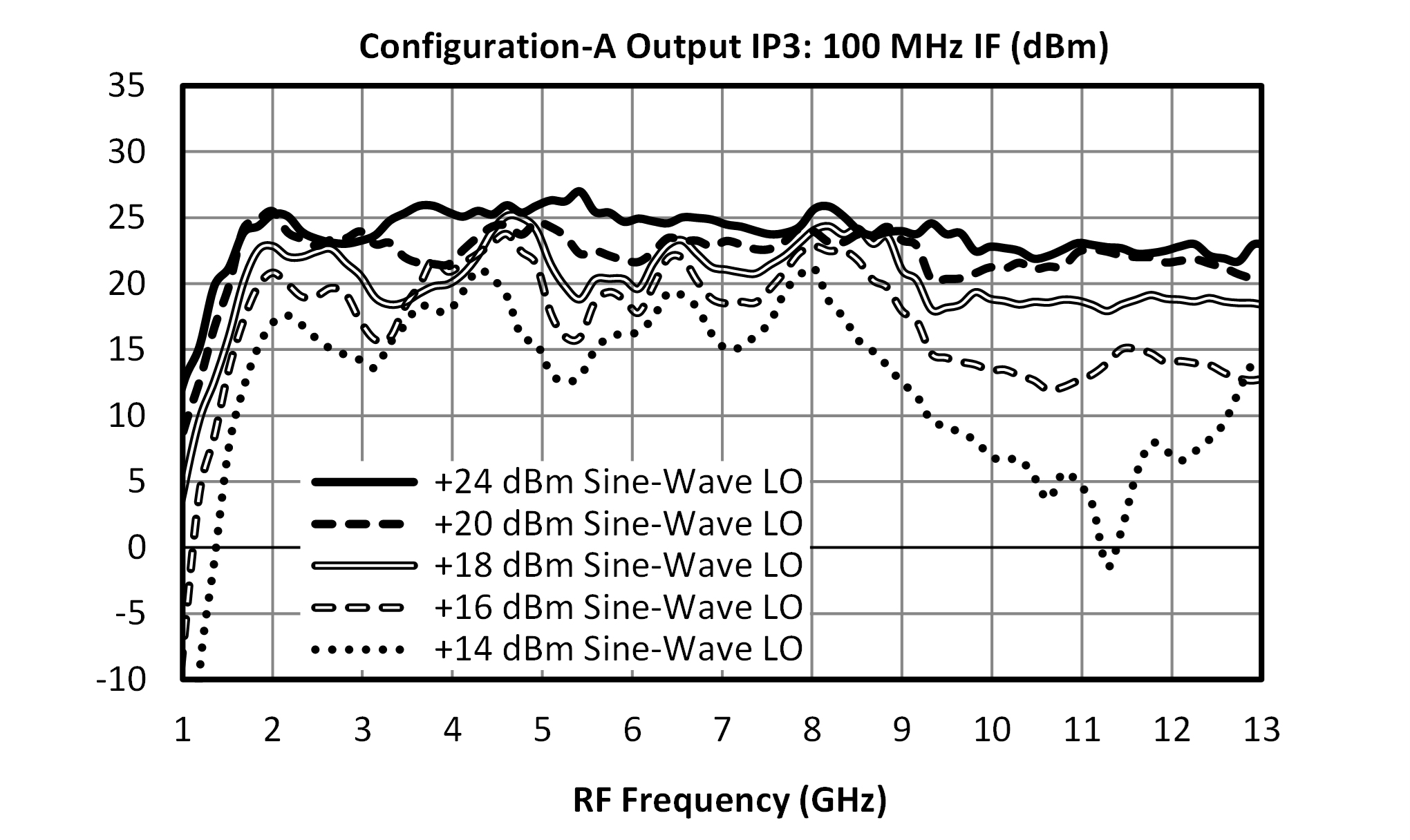
| Input IP3 3 | A | LO/RF=1.5-13 GHz IF=0.01-7 GHz LO Drive Level= 16-24 | - | 30 | - | dBm |
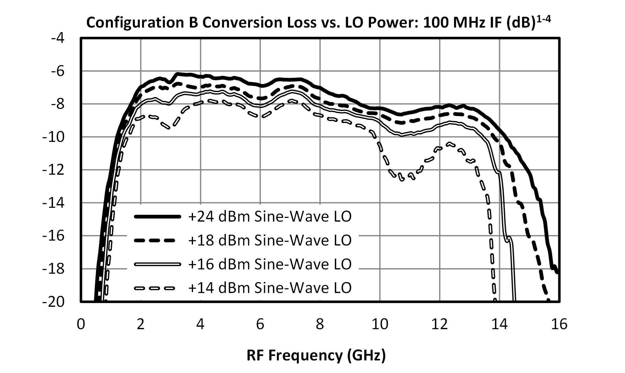
| Conversion Loss 4 | B | LO/RF=1.5-13 GHz IF=0.01-0.5 GHz LO Drive Level= 20 | - | 7.5 | - | dB |
| Conversion Loss 5 | B | LO/RF=1.5-13 GHz IF=0.5-7 GHz | - | 10 | - | dB |
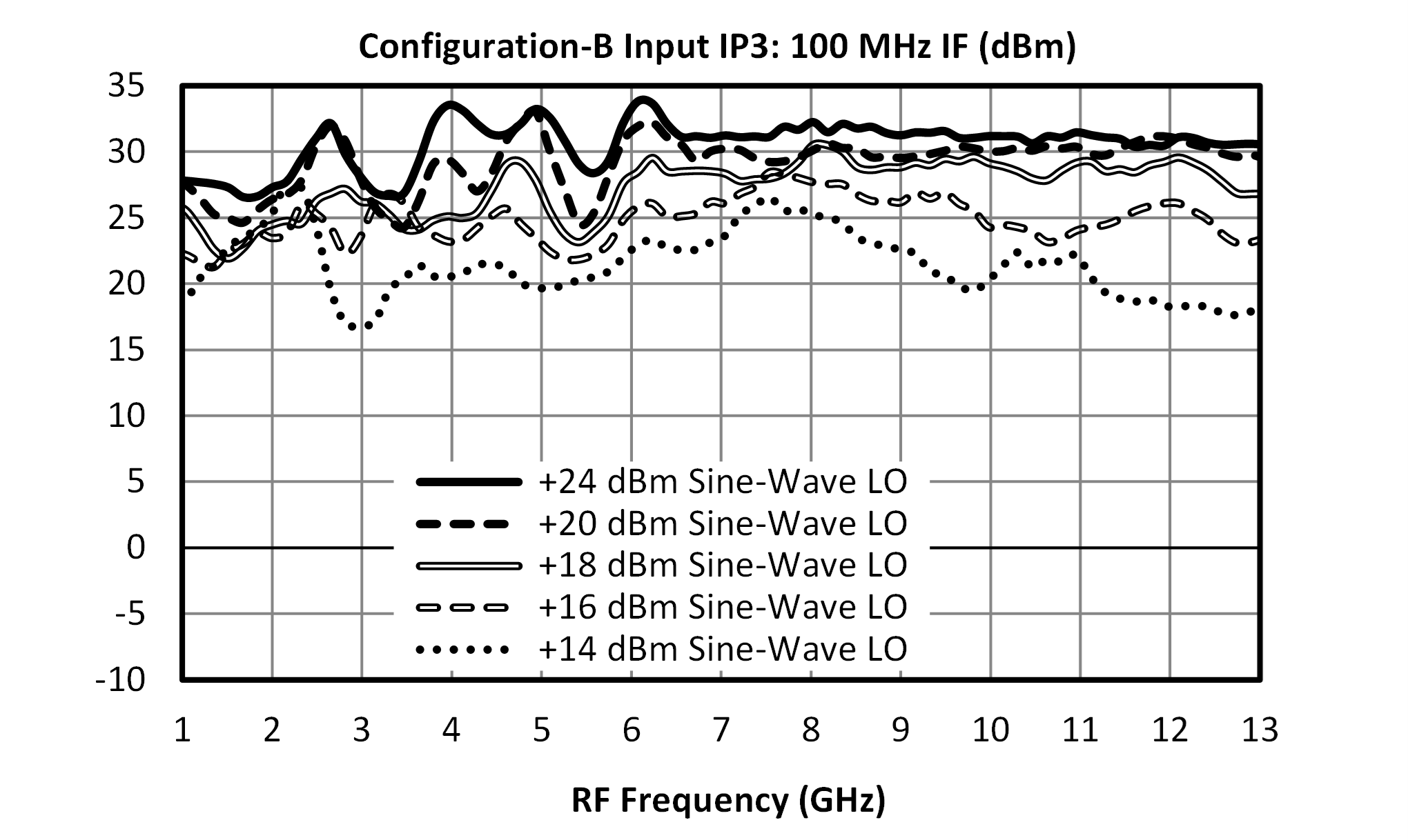
| Input IP3 6 | B | LO/RF=1.5-13 GHz IF=0.01-7 GHz LO Drive Level= 16-24 | - | 29 | - | dBm |
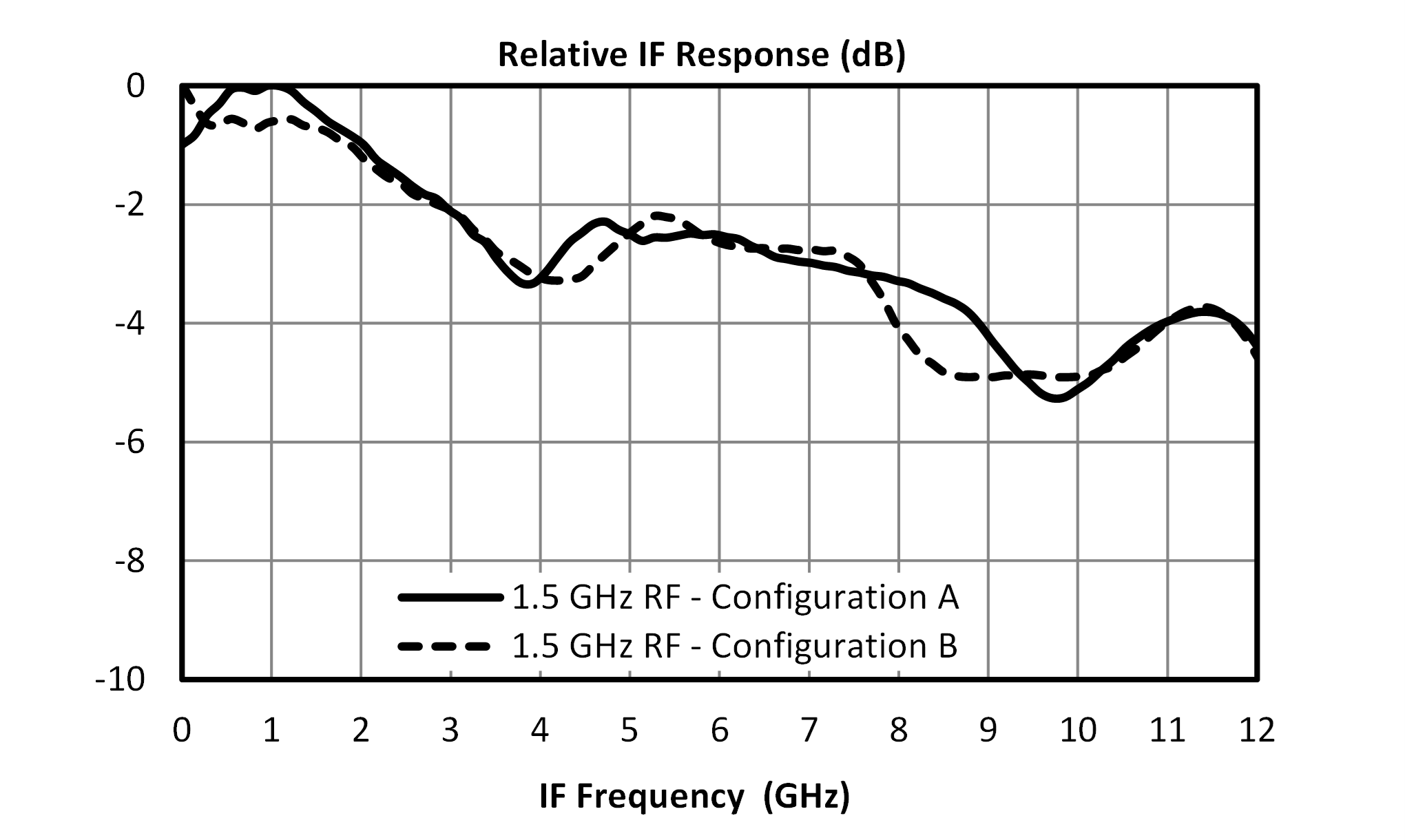
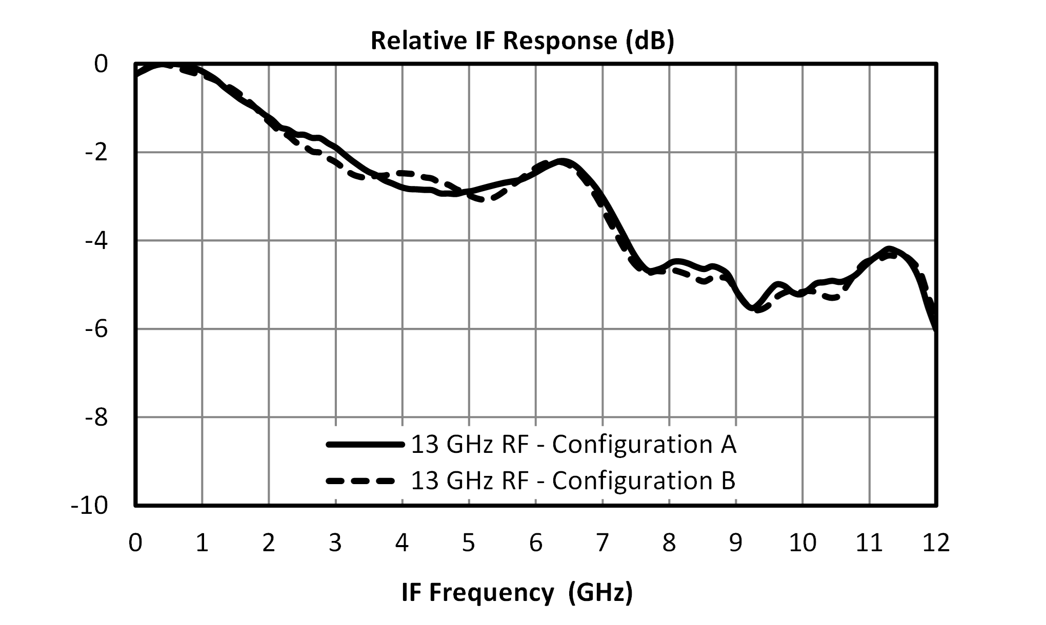
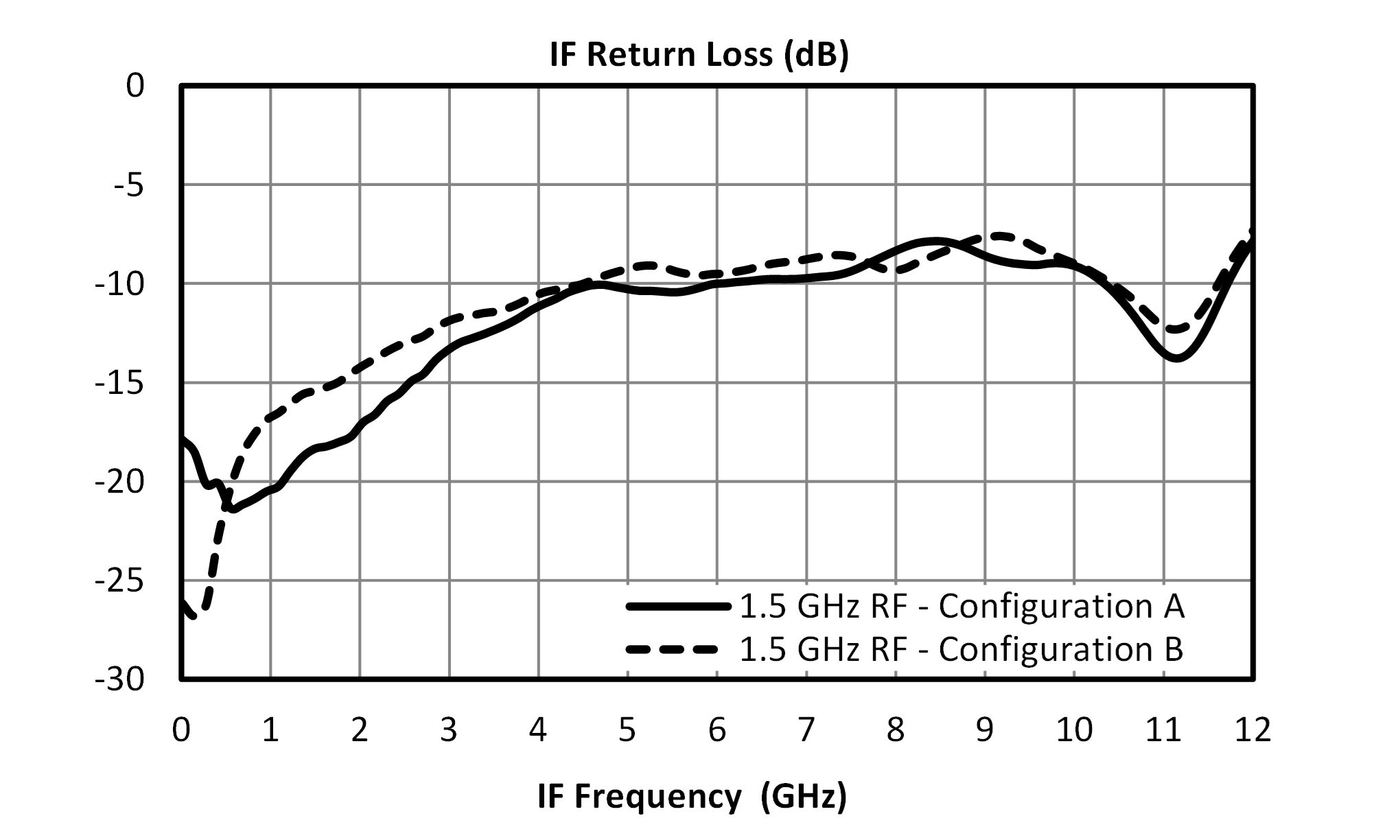
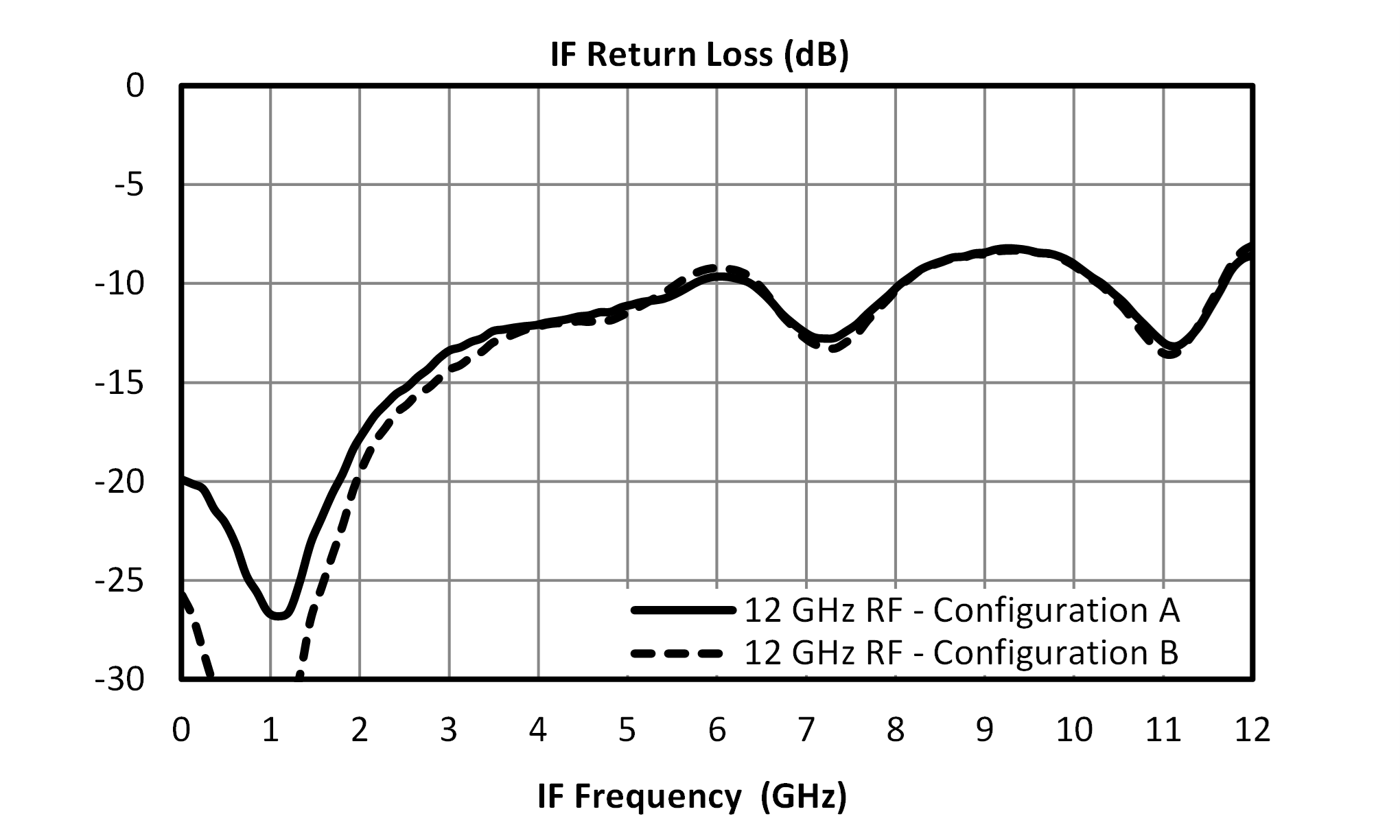
| IF Frequency Range | - | - | 0.01 | - | 7 | GHz |
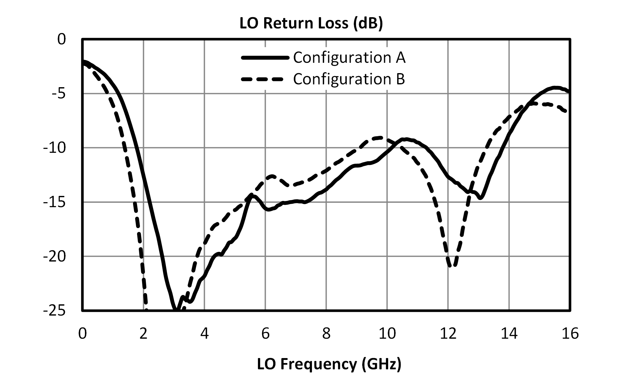
| LO Frequency Range | - | - | 1.5 | - | 13 | GHz |
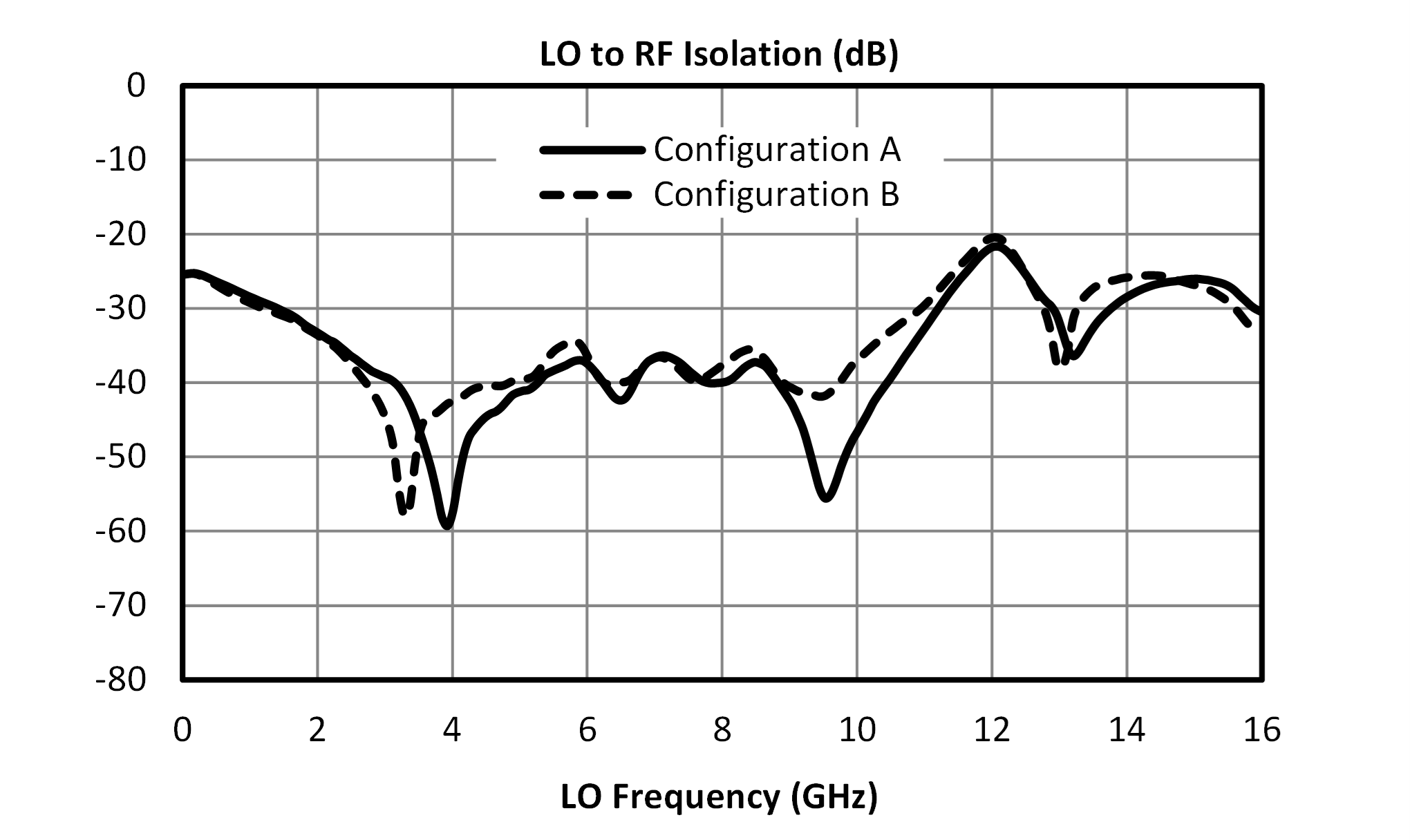
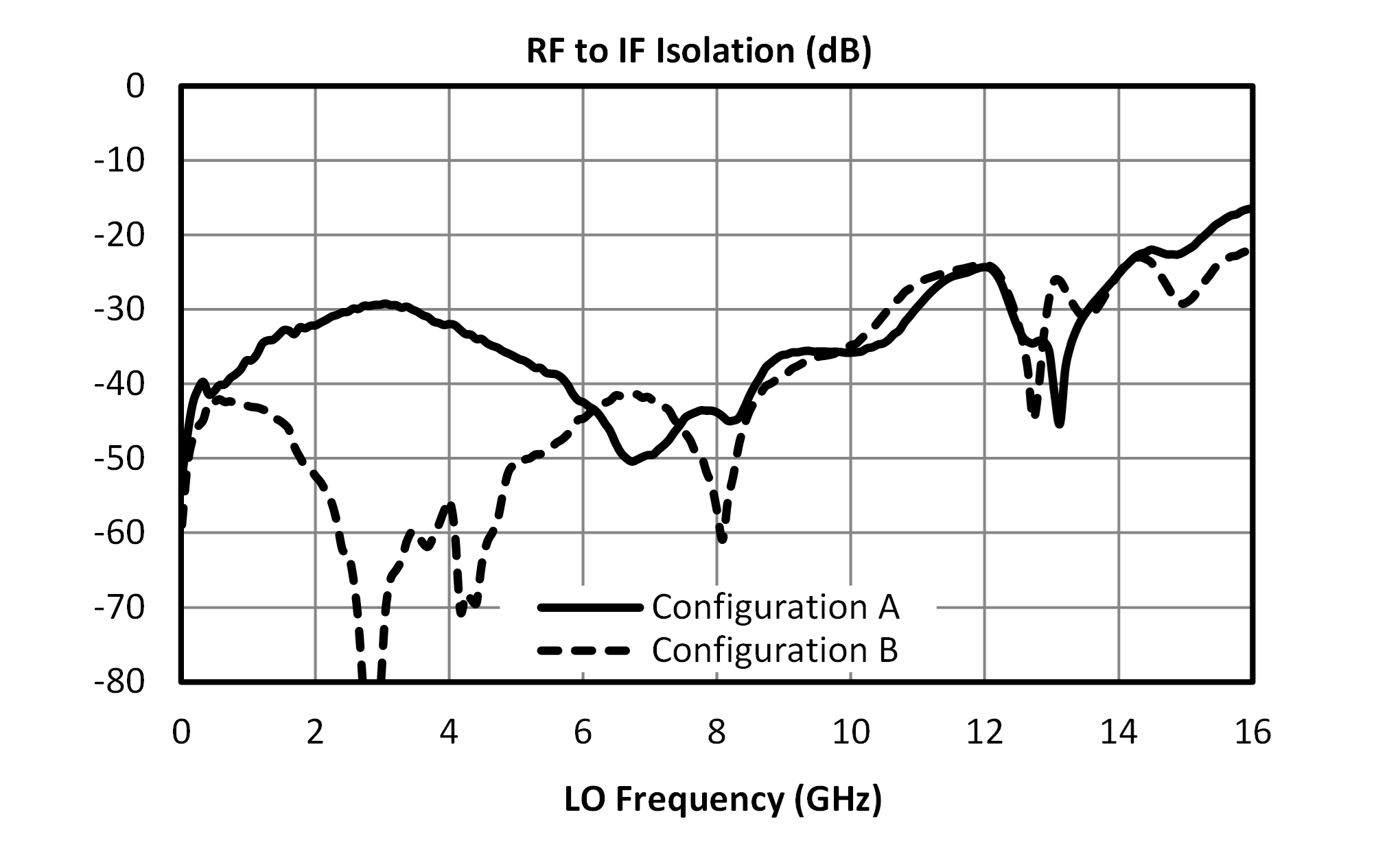
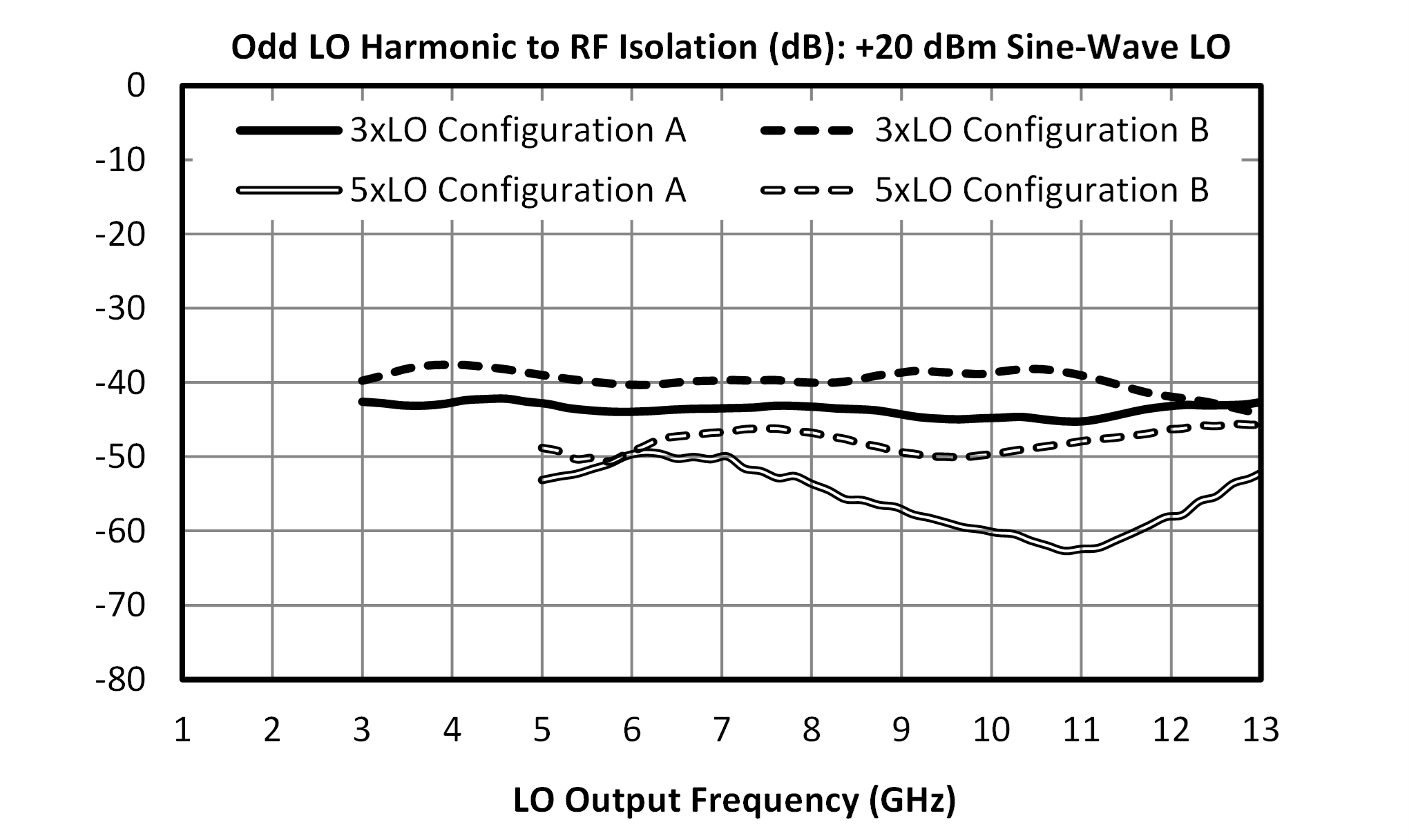
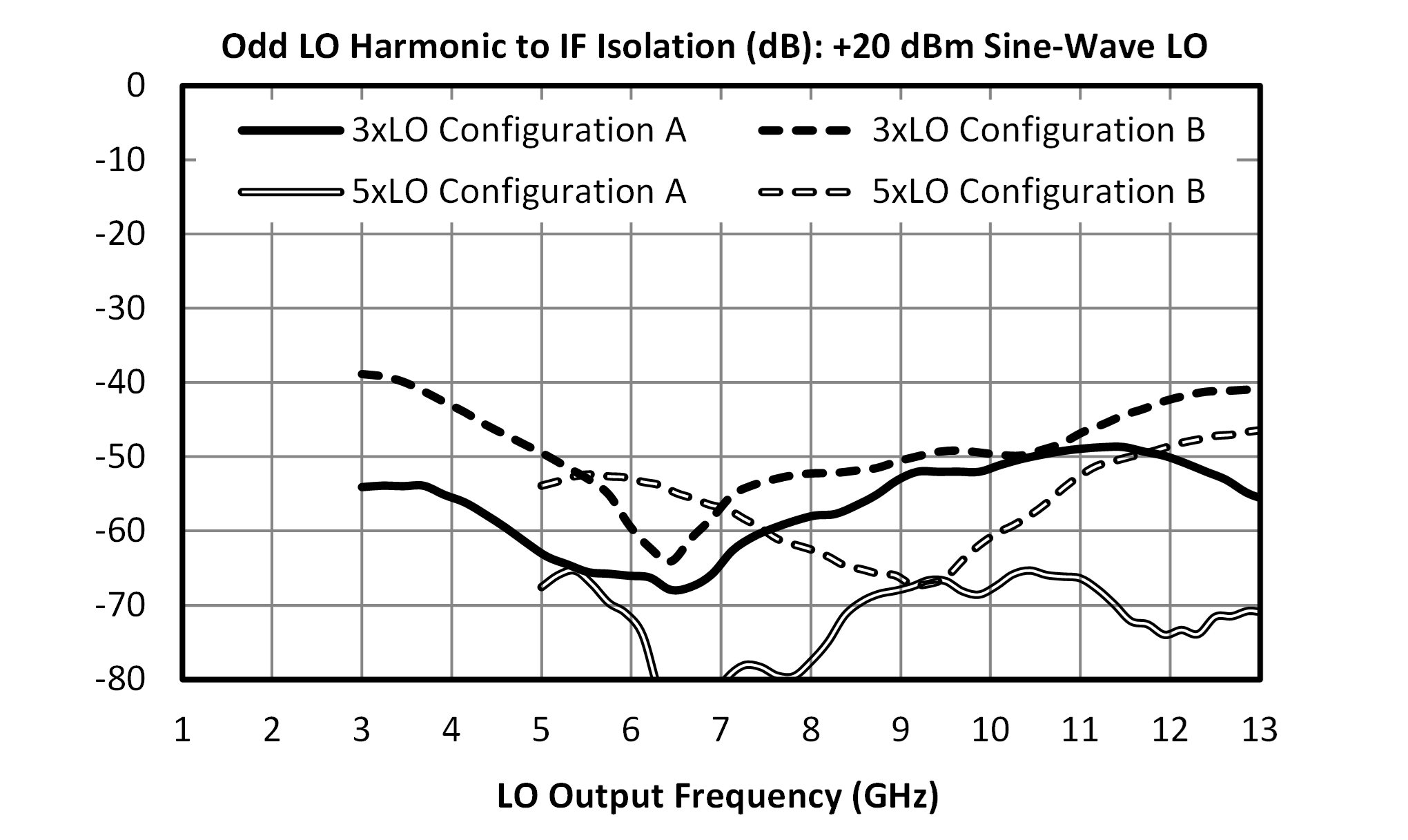
| LO-RF Isolation | - | - | - | 40 | - | dB |
| RF Frequency Range | - | - | 1.5 | - | 13 | GHz |
| Parameter | Port Configuration | Test Conditions | Min | Typ | Max | Unit |
|---|---|---|---|---|---|---|
| Conversion Loss 1 | A | LO/RF=1.5-13 GHz IF=0.01-0.5 GHz LO Drive Level= 20 | - | 7.5 | 10.5 | dB |
| Conversion Loss 2 | A | LO/RF=1.5-13 GHz IF=0.5-7 GHz | - | 10 | - | dB |
| Input IP3 3 | A | LO/RF=1.5-13 GHz IF=0.01-7 GHz LO Drive Level= 16-24 | - | 30 | - | dBm |
| Conversion Loss 4 | B | LO/RF=1.5-13 GHz IF=0.01-0.5 GHz LO Drive Level= 20 | - | 7.5 | - | dB |
| Conversion Loss 5 | B | LO/RF=1.5-13 GHz IF=0.5-7 GHz | - | 10 | - | dB |
| Input IP3 6 | B | LO/RF=1.5-13 GHz IF=0.01-7 GHz LO Drive Level= 16-24 | - | 29 | - | dBm |
| IF Frequency Range | - | - | 0.01 | - | 7 | GHz |
| LO Frequency Range | - | - | 1.5 | - | 13 | GHz |
| LO-RF Isolation | - | - | - | 40 | - | dB |
| RF Frequency Range | - | - | 1.5 | - | 13 | GHz |
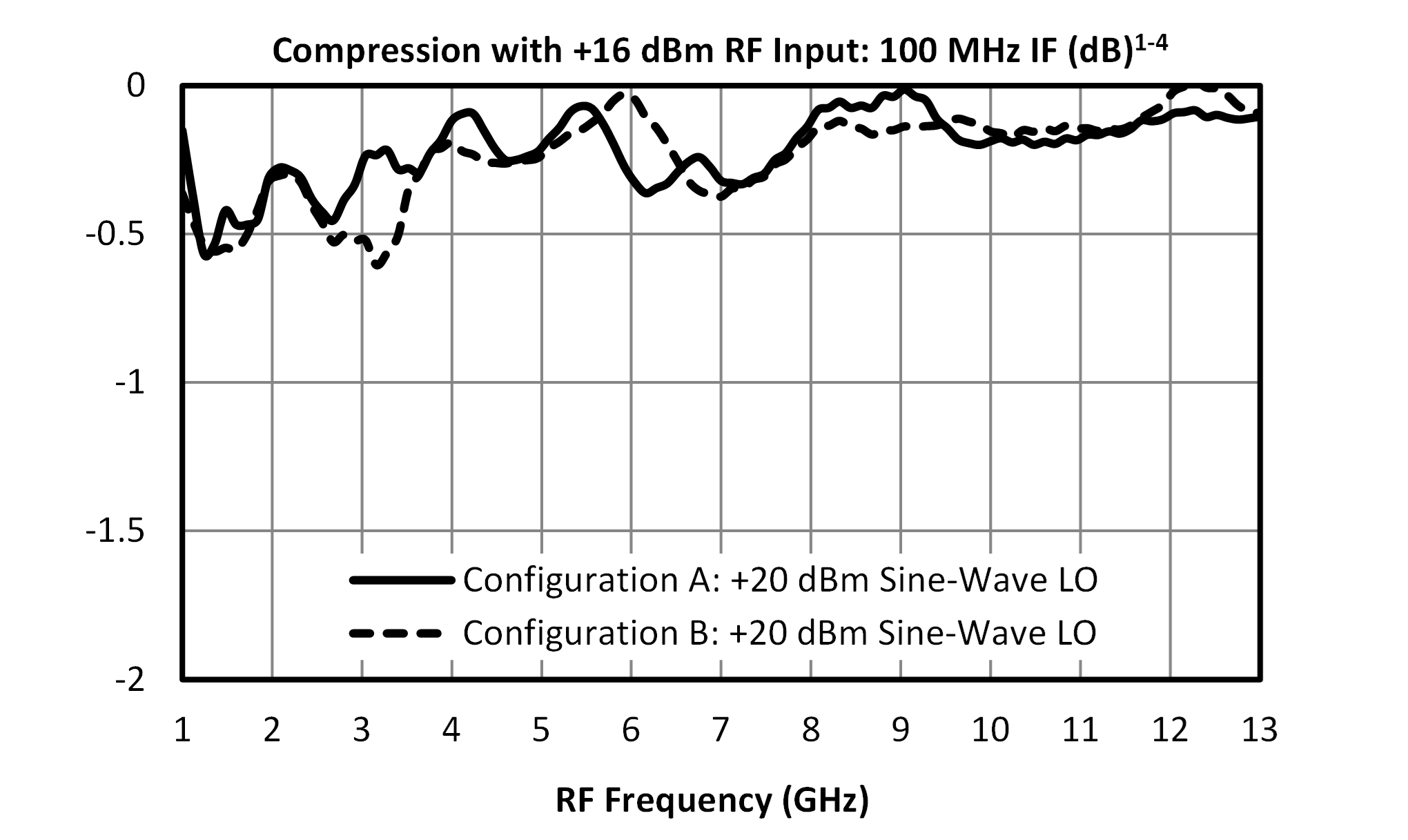
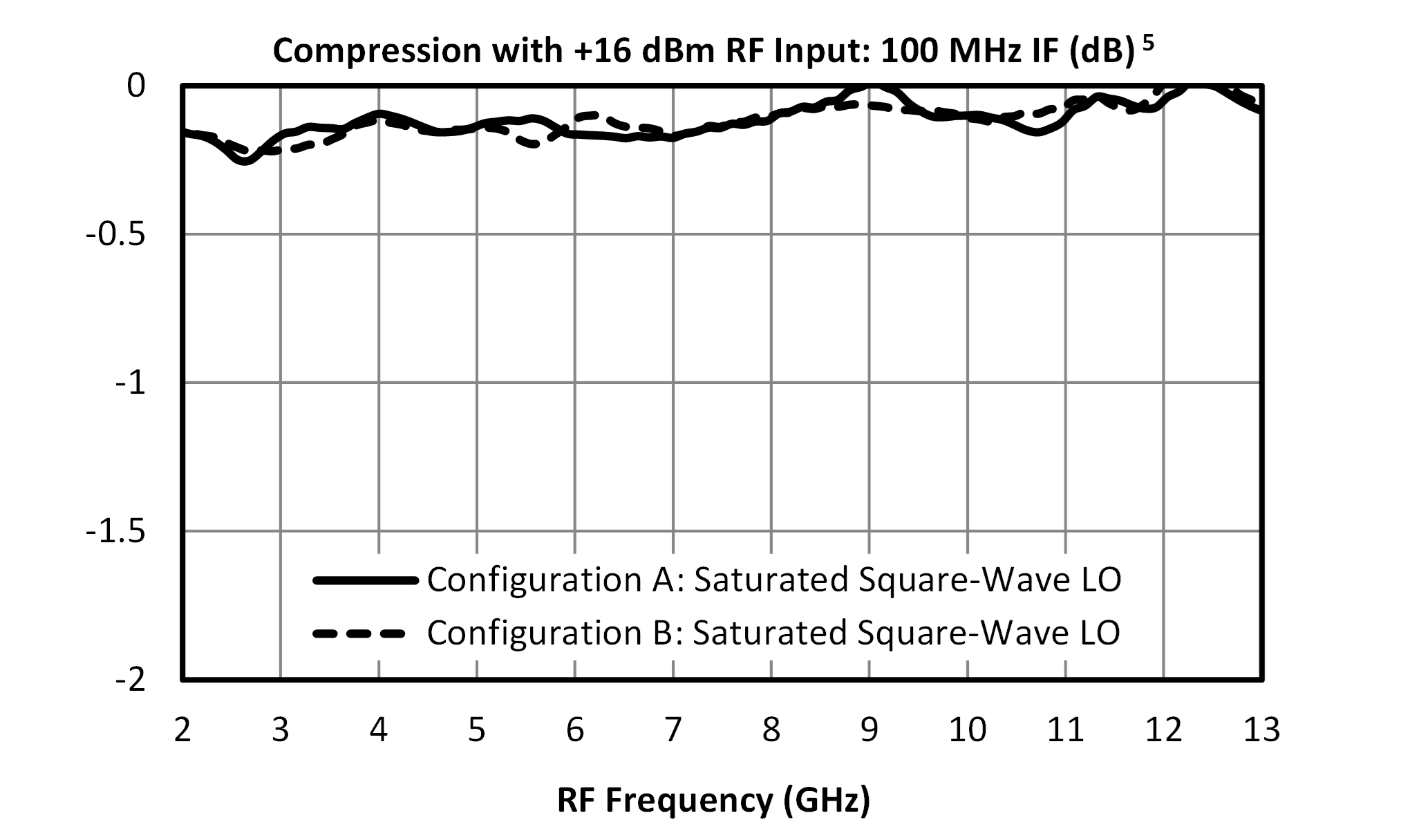
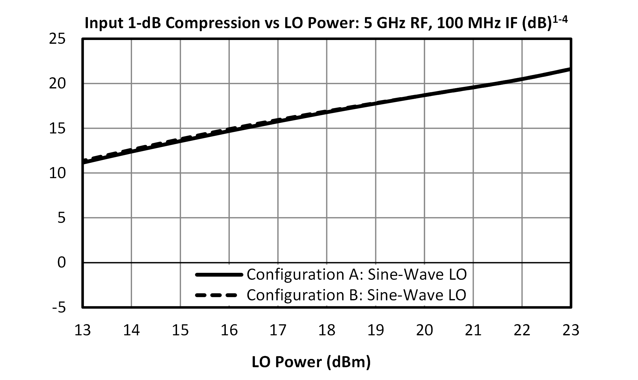
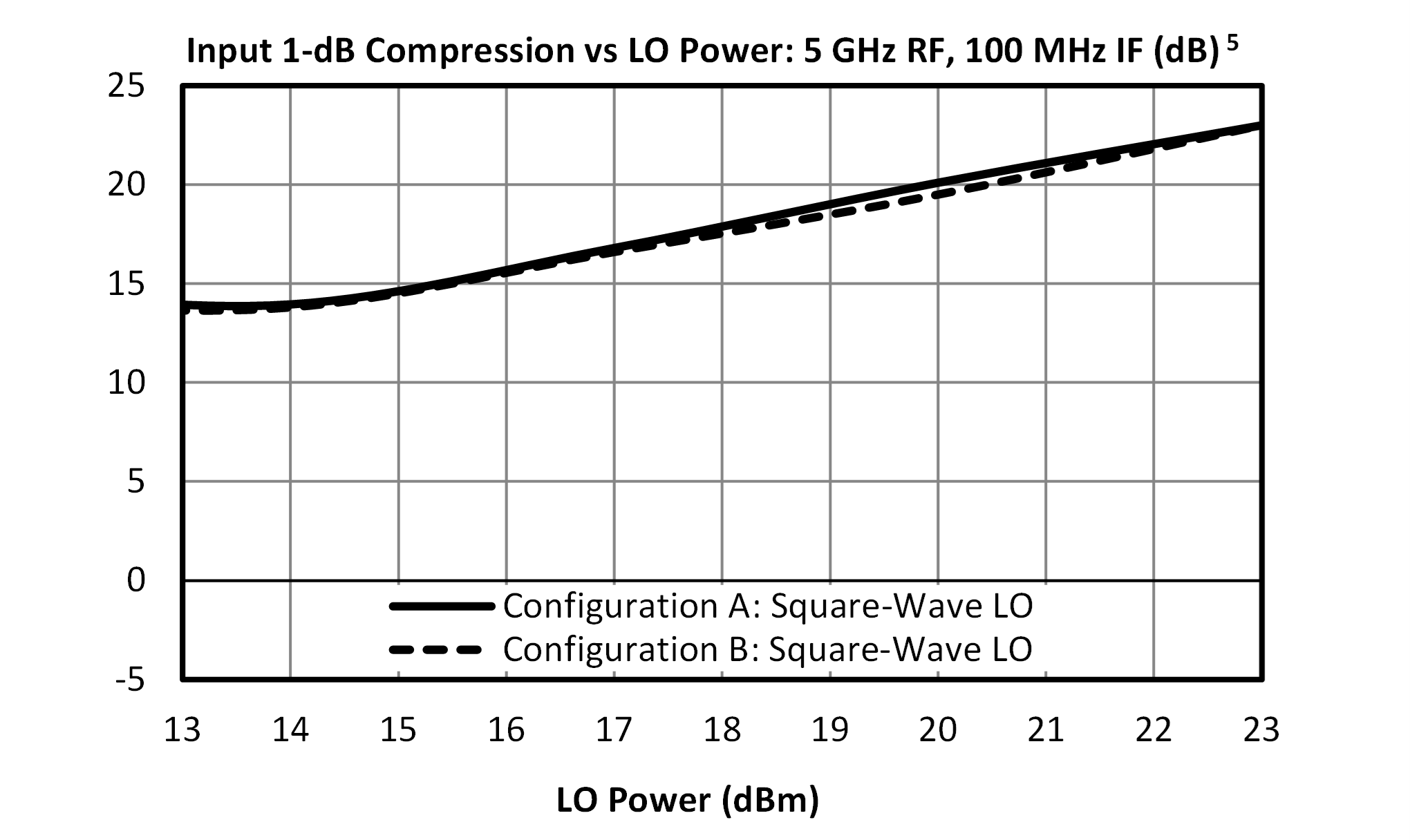
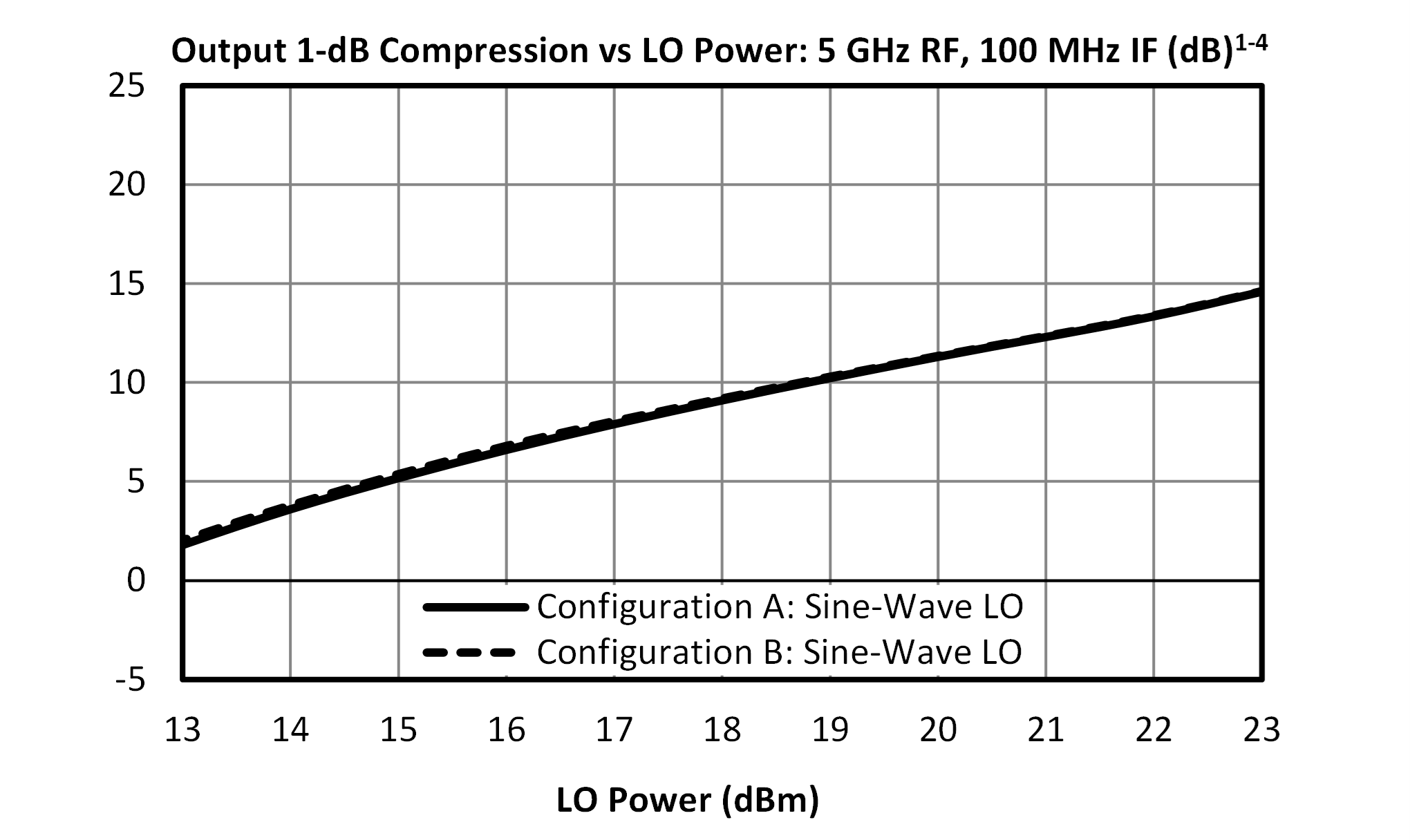
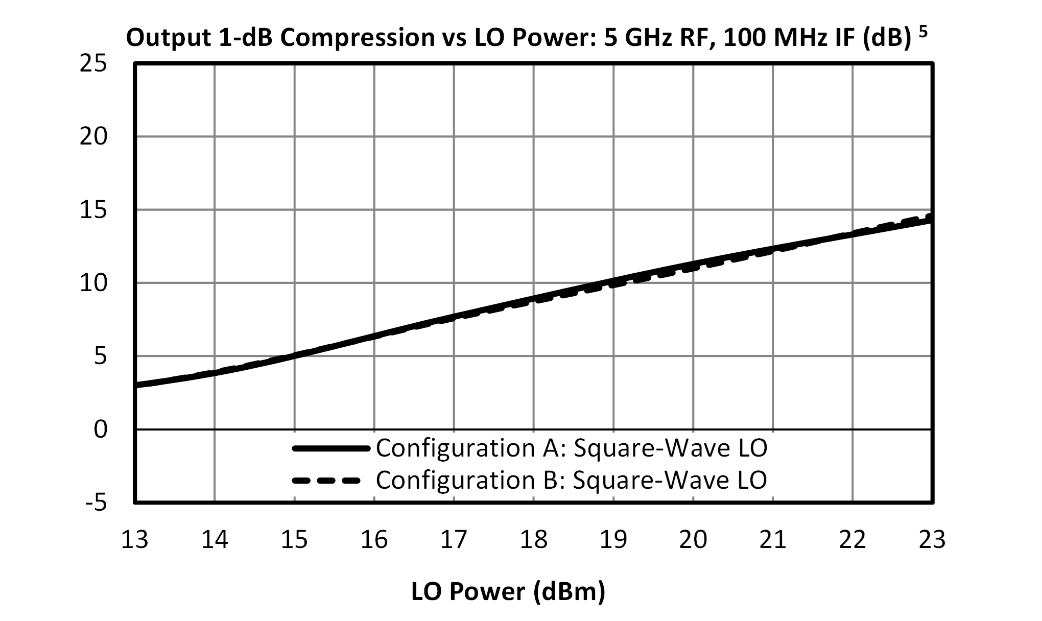
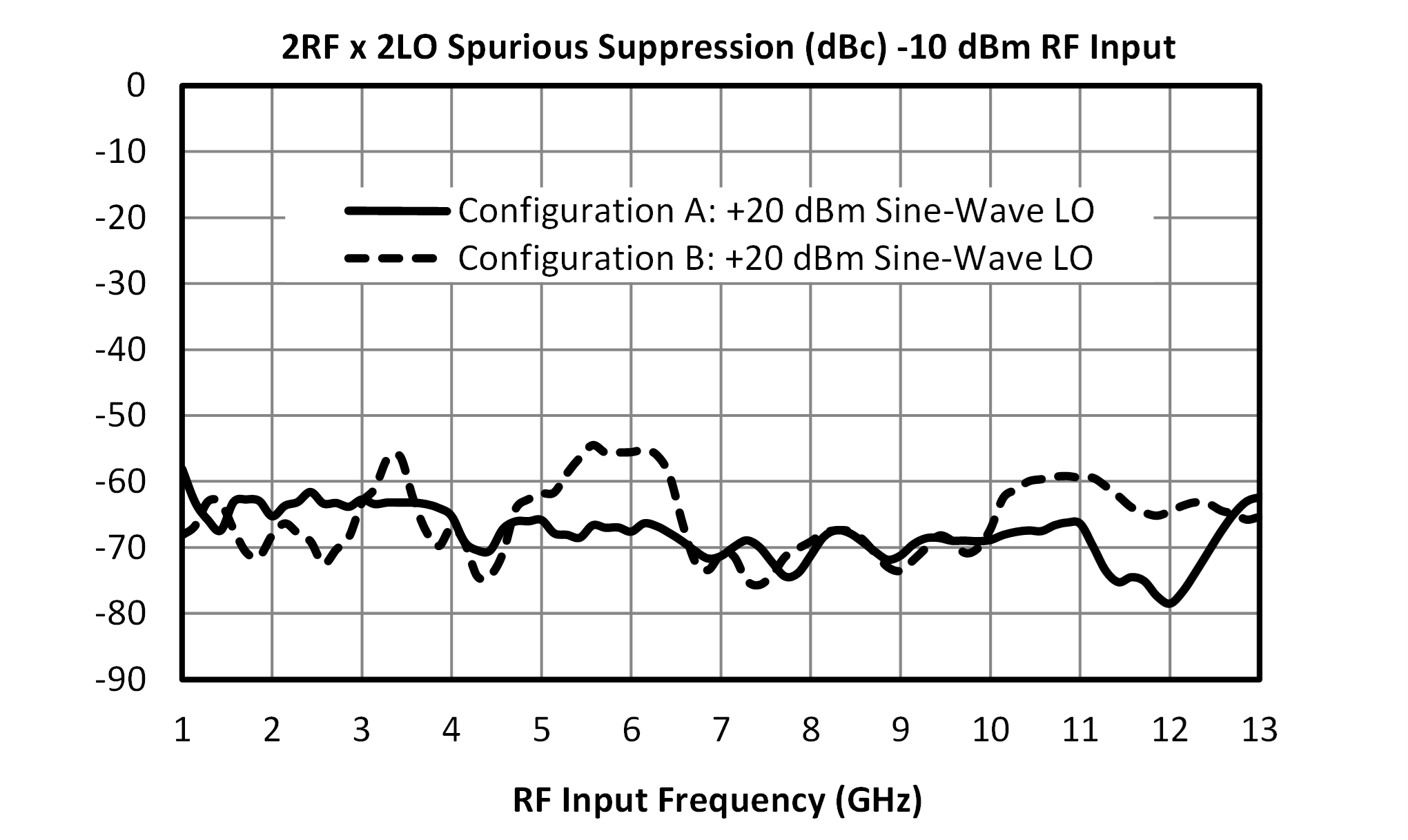
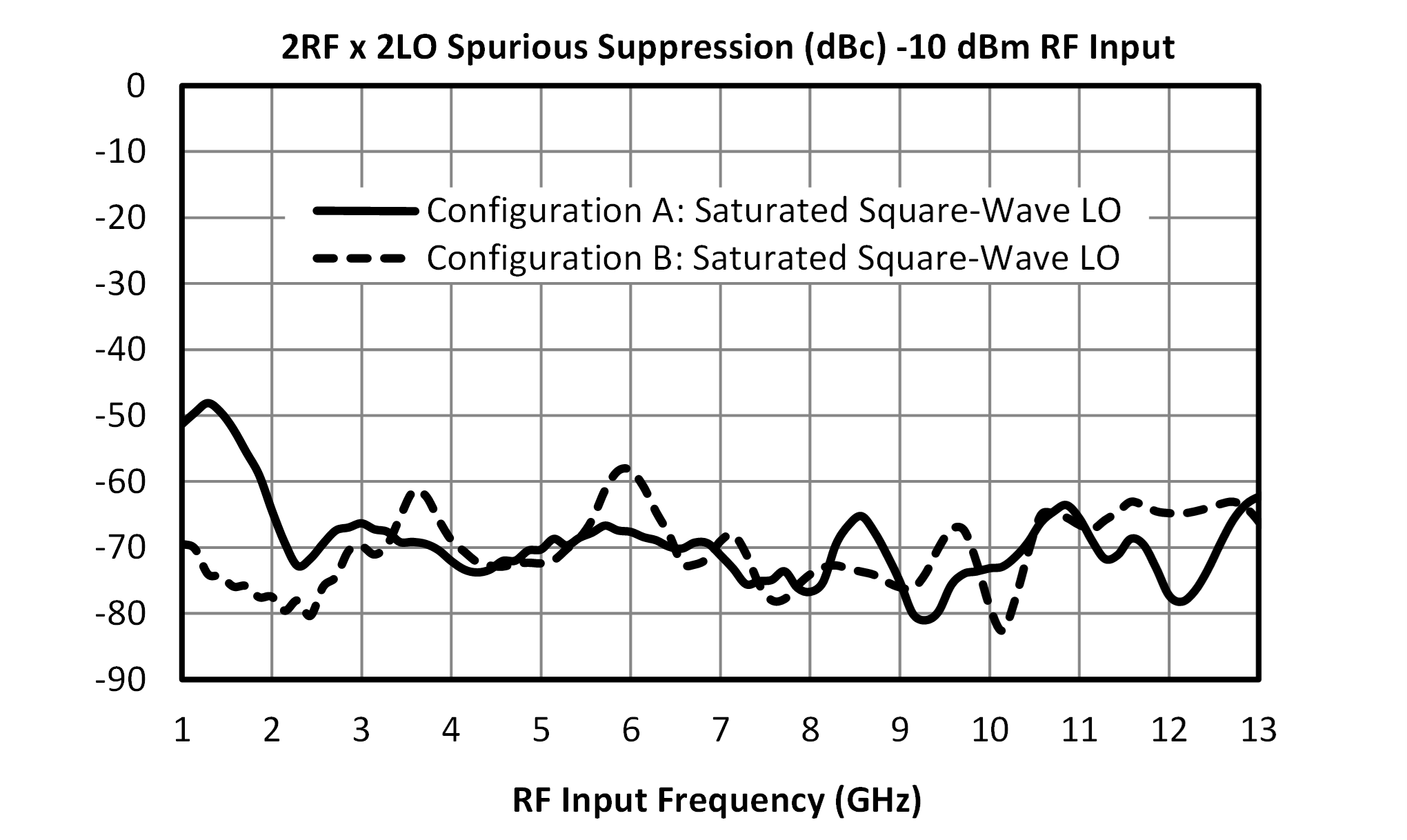
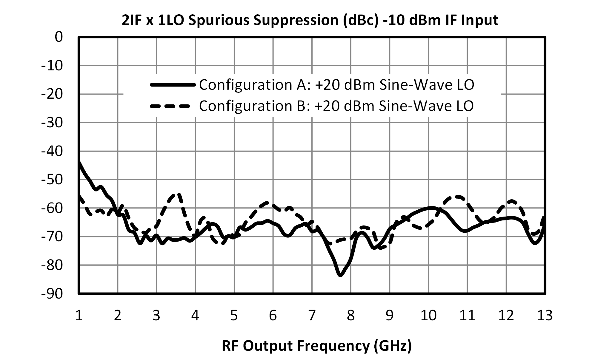
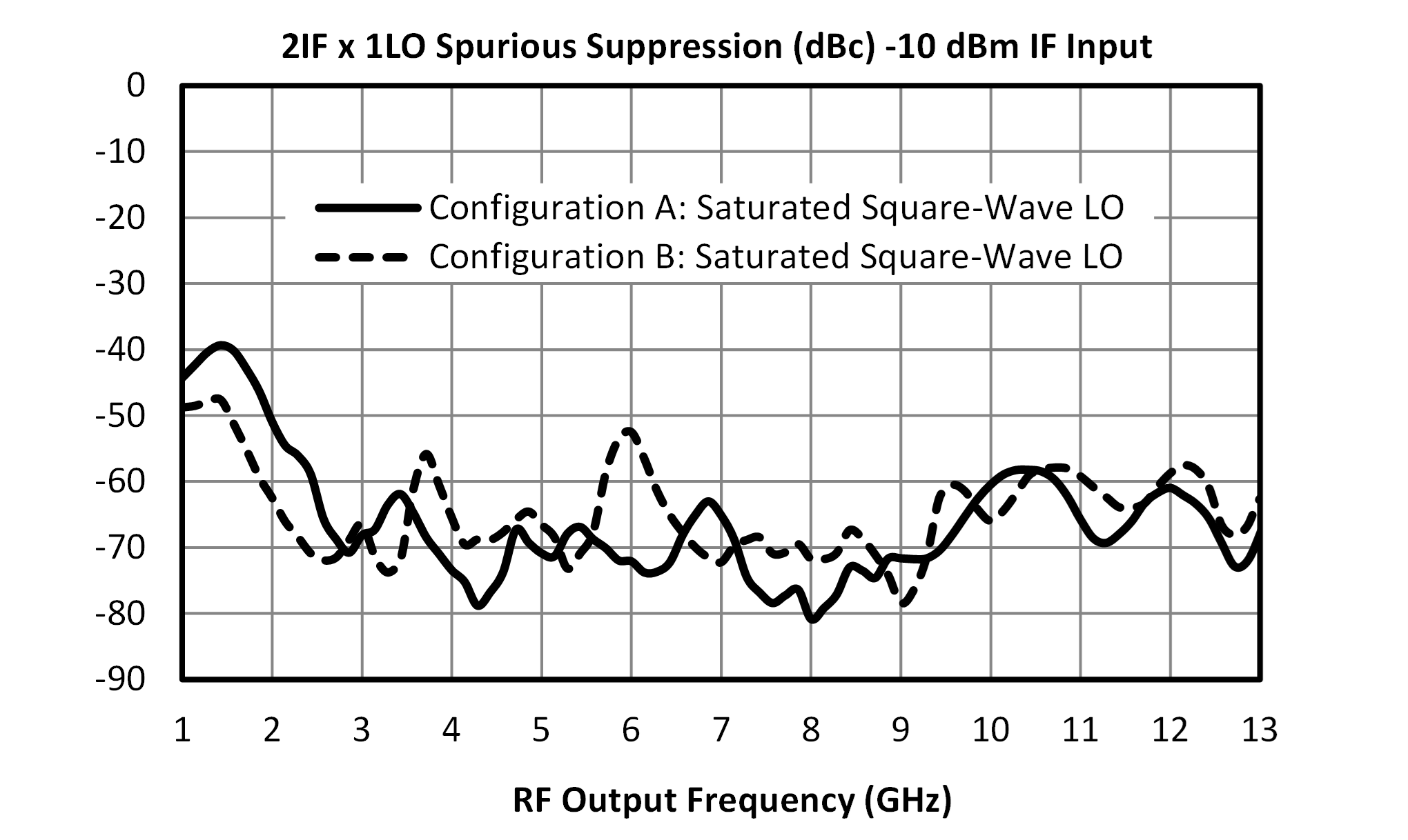
[1][2][4][5] Unless otherwise specified, Conversion Loss and Spurious data is measured with a 100 MHz fixed IF.
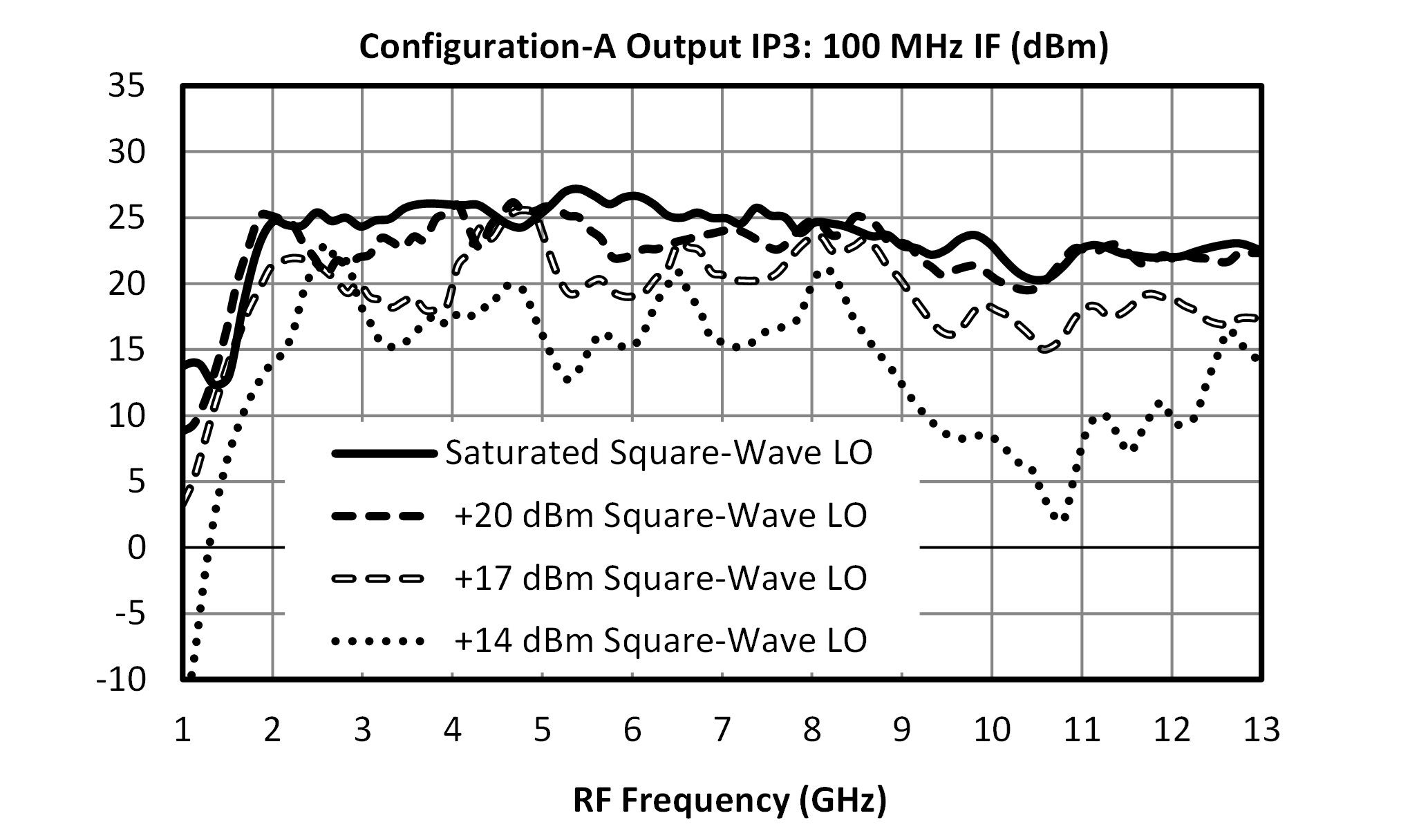
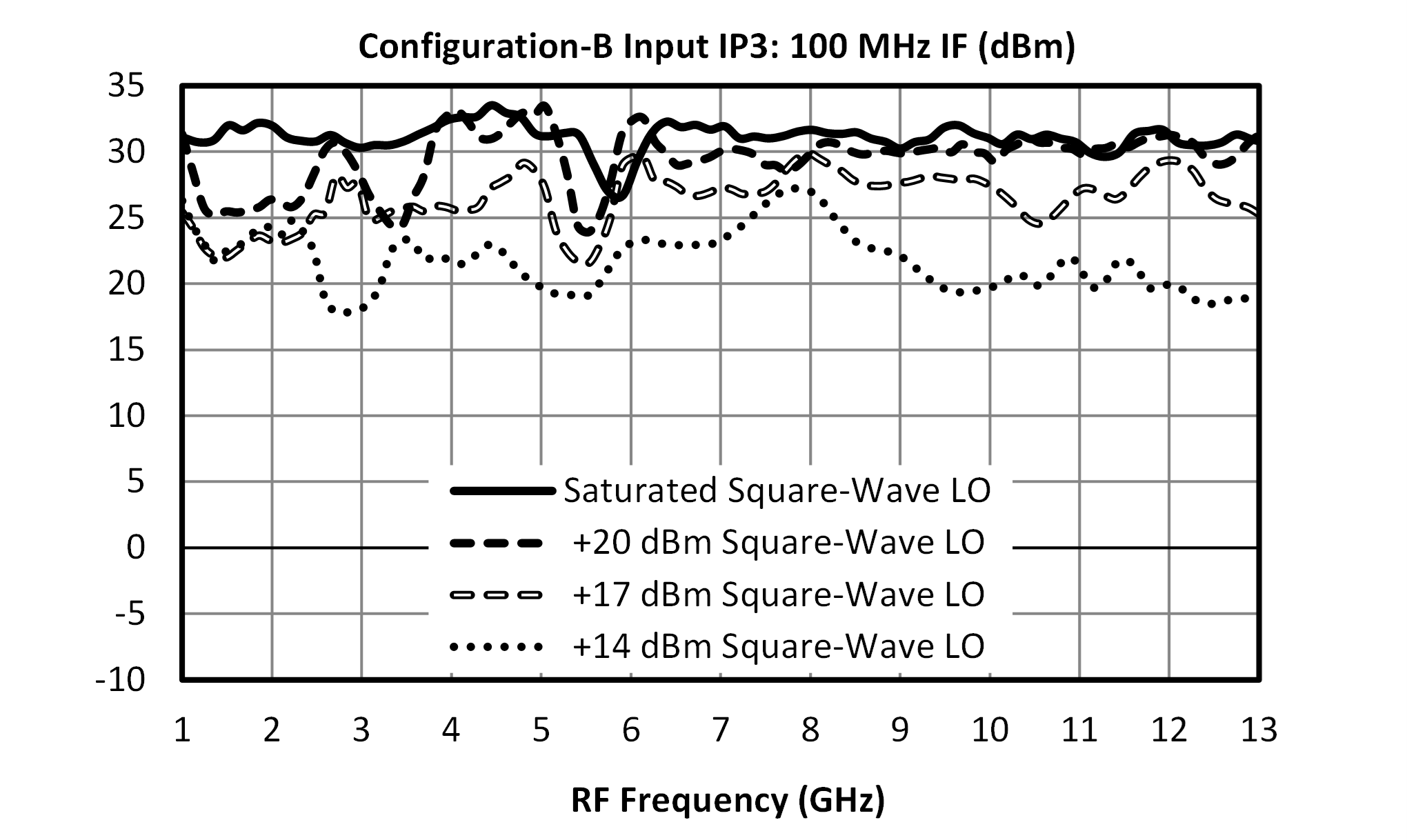
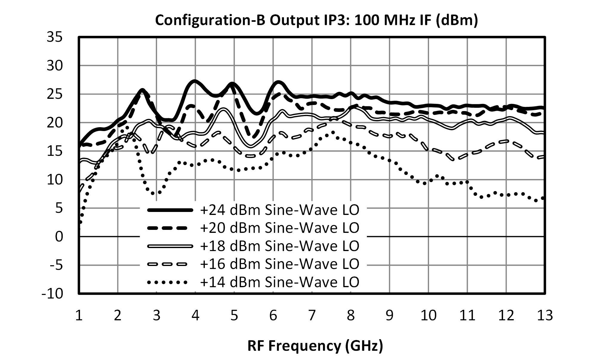
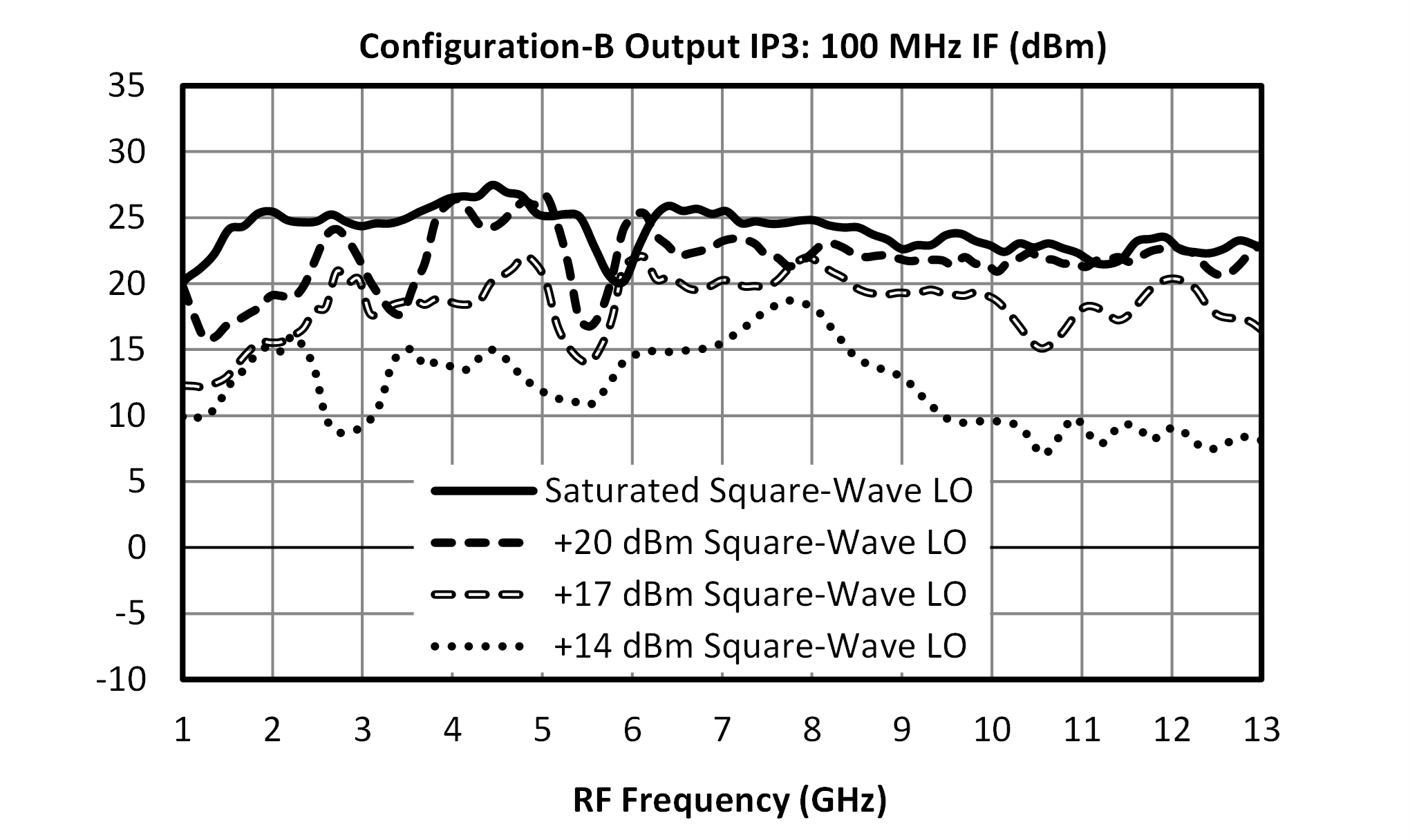
[3][6] The typical value is for a +20 dBm Sine-Wave LO. IP3 is dependent on LO drive and waveform. See plots and data sheet notes for more details.
MT3-0113HCQG-1
GaAs MMIC High Dynamic Range Mixer
MT3-0113HCQG-1
GaAs MMIC High Dynamic Range Mixer
MT3-0113HCQG-1
GaAs MMIC High Dynamic Range Mixer
MT3-0113HCQG-1
GaAs MMIC High Dynamic Range Mixer
MT3-0113HCQG-1
GaAs MMIC High Dynamic Range Mixer
MT3-0113HCQG-1
GaAs MMIC High Dynamic Range Mixer
MT3-0113HCQG-1
GaAs MMIC High Dynamic Range Mixer

