Device Overview

General Description

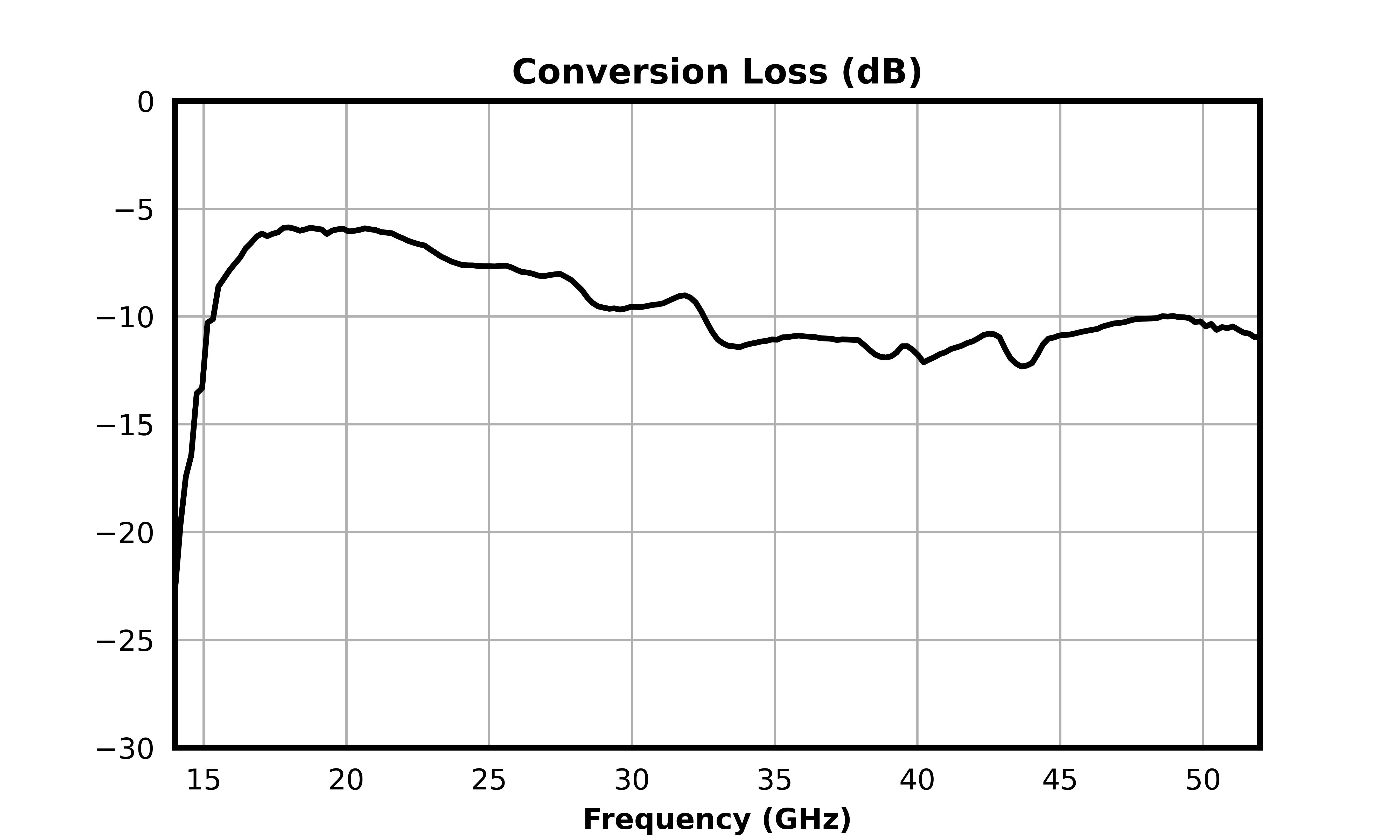
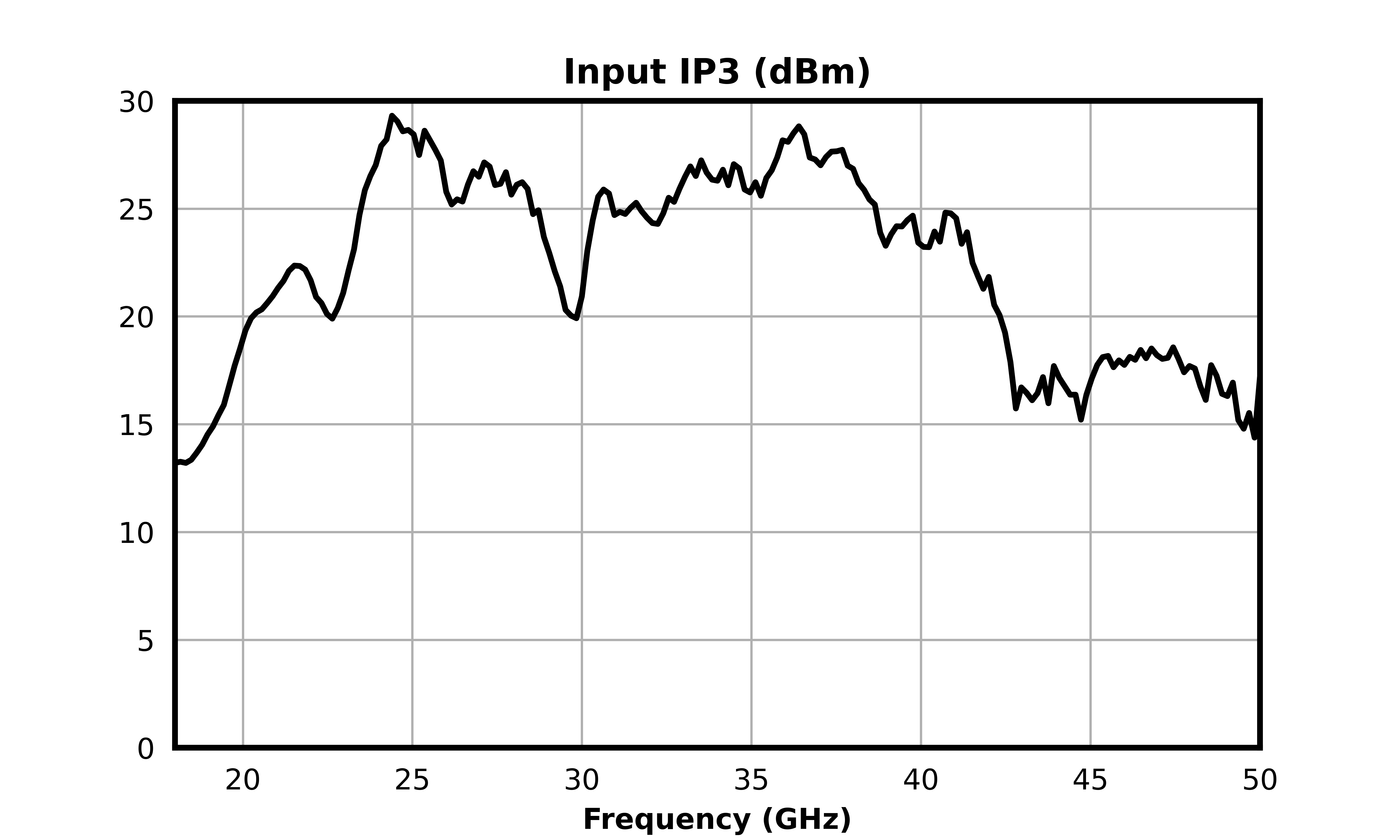
The MM1-1850HPSM-2 is a wideband GaAs MMIC double balanced mixer, operating from 18 to 50 GHz. It performs well as both an up and down converter, offering typical conversion loss of 10 dB, input IP3 of +23.5 dBm, and LO to RF isolation of 41 dB, with strong spurious suppression. The MM1-1850HPSM-2 features a wide LO drive range from +12 to +22 dBm, granting versatility across various system architectures. It is offered alongside a companion mixer the MM1-1850SSM, which is optimized for high linearity applications, giving designers a performance matched option within the same frequency band.

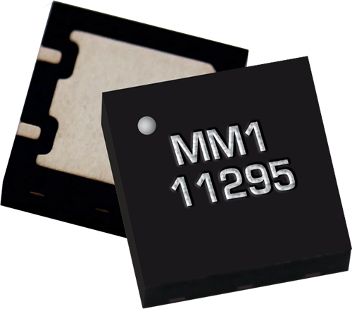
Photo of MM1-1850HPSM-2

Features

  • High Frequency Operation from 18 to 50 GHz
  • Low Conversion Loss, 10 dB Typical
  • High LO to RF isolation, 41 dB Typical
  • Small 4x4mm QFN Package

Applications

  • 5G Test Receivers
  • Electronic Warfare Scanners

Functional Block Diagram

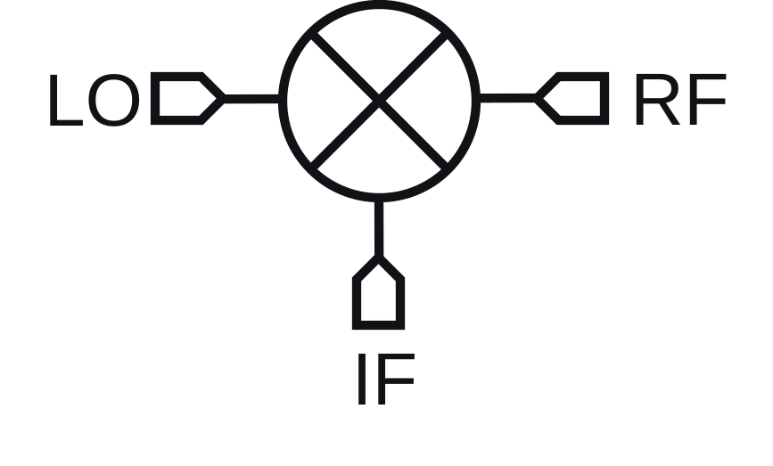
Block Diagram

Part Ordering Options

Part NumberDescriptionPackageGreen StatusProduct LifecycleExport Classification
MM1-1850HPSM-2GaAs MMIC Double Balanced Mixer DFN

REACH

RoHS

ReleasedEAR99
EVB-MM1-1850HPEvaluation Board, GaAs MMIC 18 - 50 GHz Double-balanced MixerEVAL

REACH

RoHS

ReleasedEAR99

Table Of Contents

Revision History

Revision CodeRevision DateComment
-2026-05-28Initial Release

Rev: - | Copyright © 2026 Marki Microwave LLC.

2

Port Configuration and Functions

Port Diagram

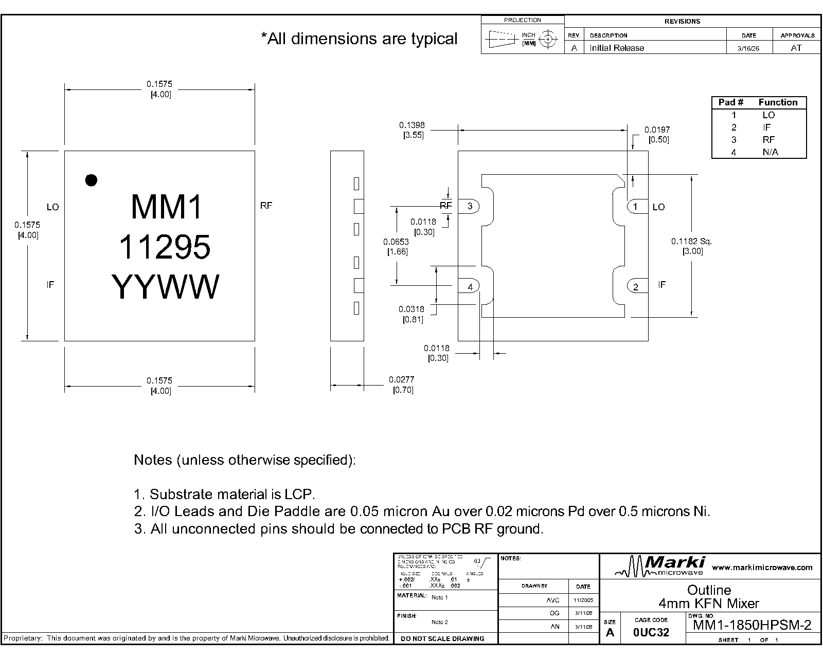
A bottom-up view of the MM1-1850HPSM’s SM package outline drawing is shown below. The MM1-1850HPSM has the input and output ports given in Port Functions. The MM1-1850HPSM can be used in either an up or down conversion. For configuration A, input the LO into pin 1, use pin 3 for the RF, and pin 2 for the IF. For configuration B, input the LO into pin 3, use pin 1 for the RF, and pin 2 for the IF.
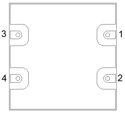
Diagram of the port configuration for MM1-1850HPSM-2

Port Functions

Configuration A

PortFunctionDescriptionDC Equivalent
Circuit
GNDGround SM package ground path is provided through the ground paddle. Equivalent circuit for the Ground
Pin 1LO Pin 1 is DC open and AC matched to 50 Ohms from 18 to 50 GHz. Equivalent circuit for the LO
Pin 2IF Port 2 is DC coupled to the diodes. Blocking capacitor is optional.Equivalent circuit for the IF
Pin 3RF Pin 3 is DC open and AC matched to 50 Ohms from 18 to 50 GHzEquivalent circuit for the RF

Rev: - | Copyright © 2026 Marki Microwave LLC.

3

Configuration B

PortFunctionDescriptionDC Equivalent
Circuit
GNDGround SM package ground path is provided through the ground paddle. Equivalent circuit for the Ground
Pin 1RF Pin 1 is DC open and AC matched to 50 Ohms from 18 to 50 GHz. Equivalent circuit for the RF
Pin 2IF Port 2 is DC coupled to the diodes. Blocking capacitor is optional.Equivalent circuit for the IF
Pin 3LO Pin 3 is DC open and AC matched to 50 Ohms from 18 to 50 GHzEquivalent circuit for the LO

Rev: - | Copyright © 2026 Marki Microwave LLC.

4

Specifications

Absolute Maximum Ratings

The Absolute Maximum Ratings indicate limits beyond which damage may occur to the device. If these limits are exceeded, the device may be inoperable or have a reduced lifetime.

ParameterMaximum RatingUnit
Power Handling, at any Port 30dBm
Maximum Operating Temperature 100°C
Maximum Storage Temperature 125°C
Minimum Operating Temperature -55°C
Minimum Storage Temperature -65°C

Package Information

ParameterDetailsRating
ESD250 to < 500 VoltsHBM Class 1A
Dimensions-4 x 4 mm
Moisture Sensitivity Level-MSL 1

The Recommended Operating Conditions indicate the limits, inside which the device should be operated, to guarantee the performance given in Electrical Specifications Operating outside these limits may not necessarily cause damage to the device, but the performance may degrade outside the limits of the electrical specifications. For limits, above which damage may occur, see Absolute Maximum Ratings.

ParameterMinNominalMaxUnit
Ambient Temperature -25-°C
LO Input Power 12-22dBm

Rev: - | Copyright © 2026 Marki Microwave LLC.

5

Electrical Specifications

The electrical specifications apply at TA=+25°C in a 50Ω system. Typical data shown is for a down conversion application with a +18dBm sine wave LO input. Specifications shown for configuration A. Configuration B may be suitable for conversions below 45 GHz.

ParameterPort ConfigurationTest ConditionsMinTypMaxUnit
Conversion Loss 1ARF = 18 - 50 GHz
LO = 18 - 45 GHz
IF = 0.2 - 21 GHz
-10-dB
IF Frequency Range --0-21GHz
Input IP3 ARF/LO = 18 - 50 GHz
IF = DC - 0.2 GHz
-23.5-dBm
Input P1dB ---9-dBm
LO Frequency Range A-18-45GHz
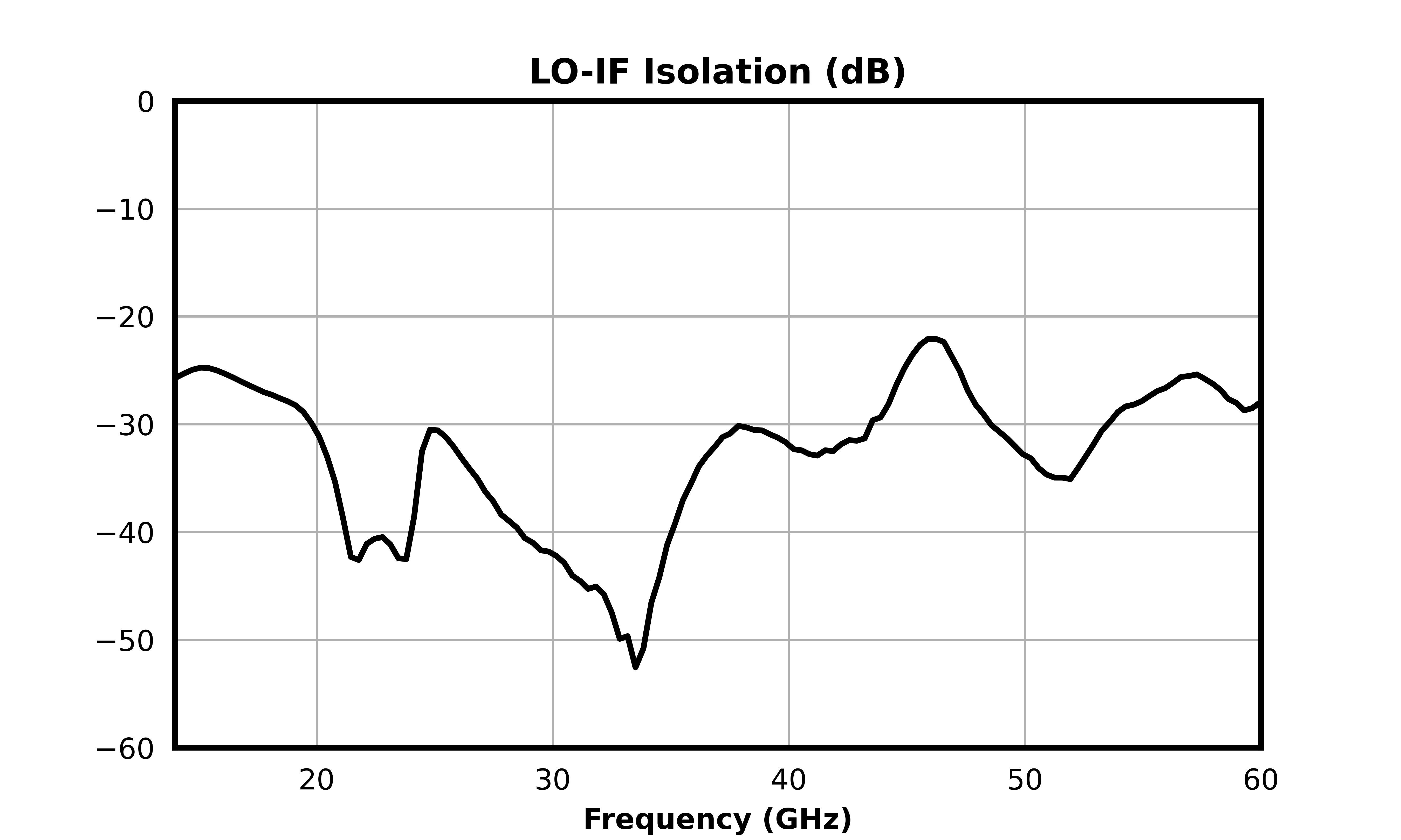
LO-IF Isolation AIF/LO = 18 - 50 GHz
-33-dB
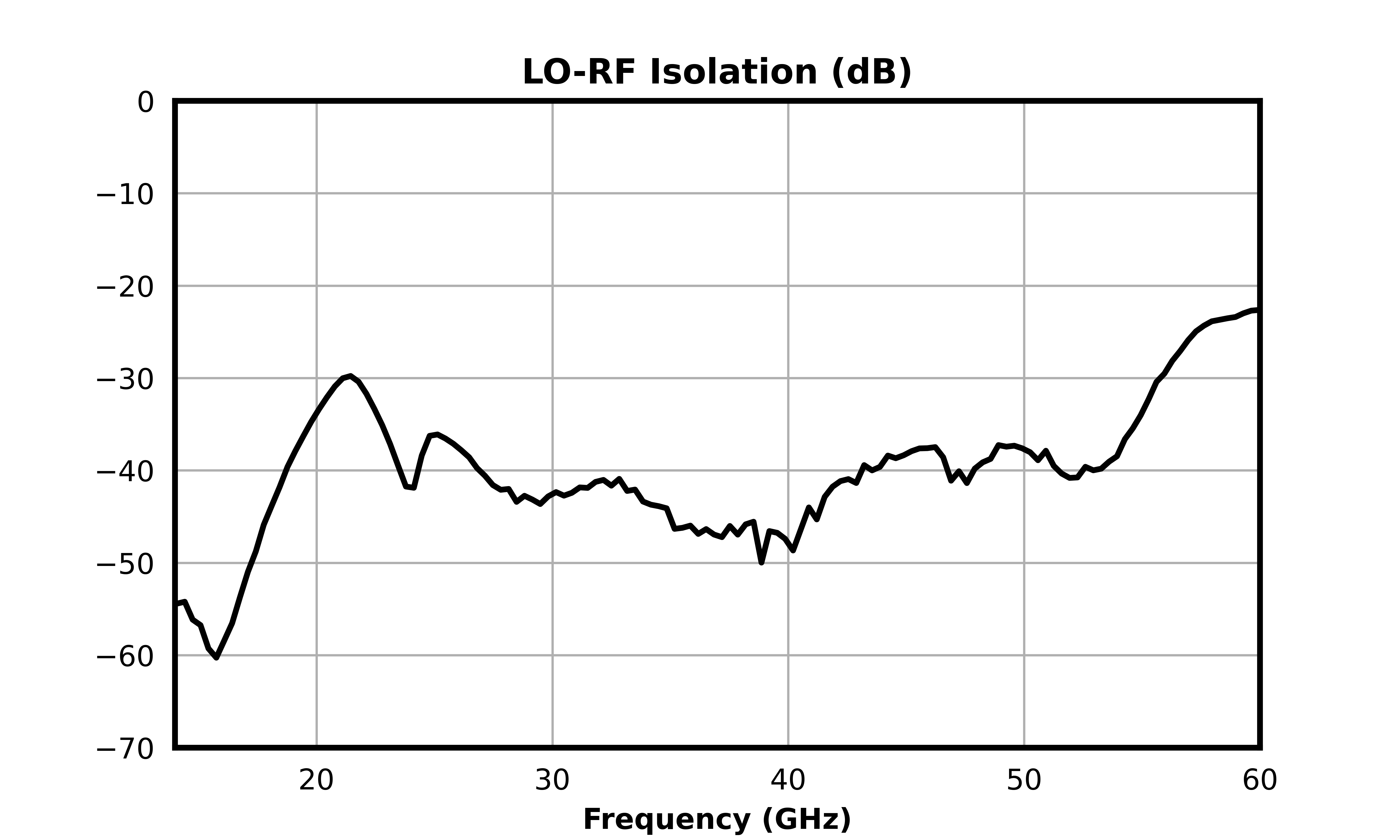
LO-RF Isolation ARF/LO = 18 - 50 GHz
-41-dB
Noise Figure 2-RF = 18 - 50 GHz
LO = 18 - 45 GHz
IF = DC - 0.2 GHz
-10-dB
RF Frequency Range A-18-50GHz
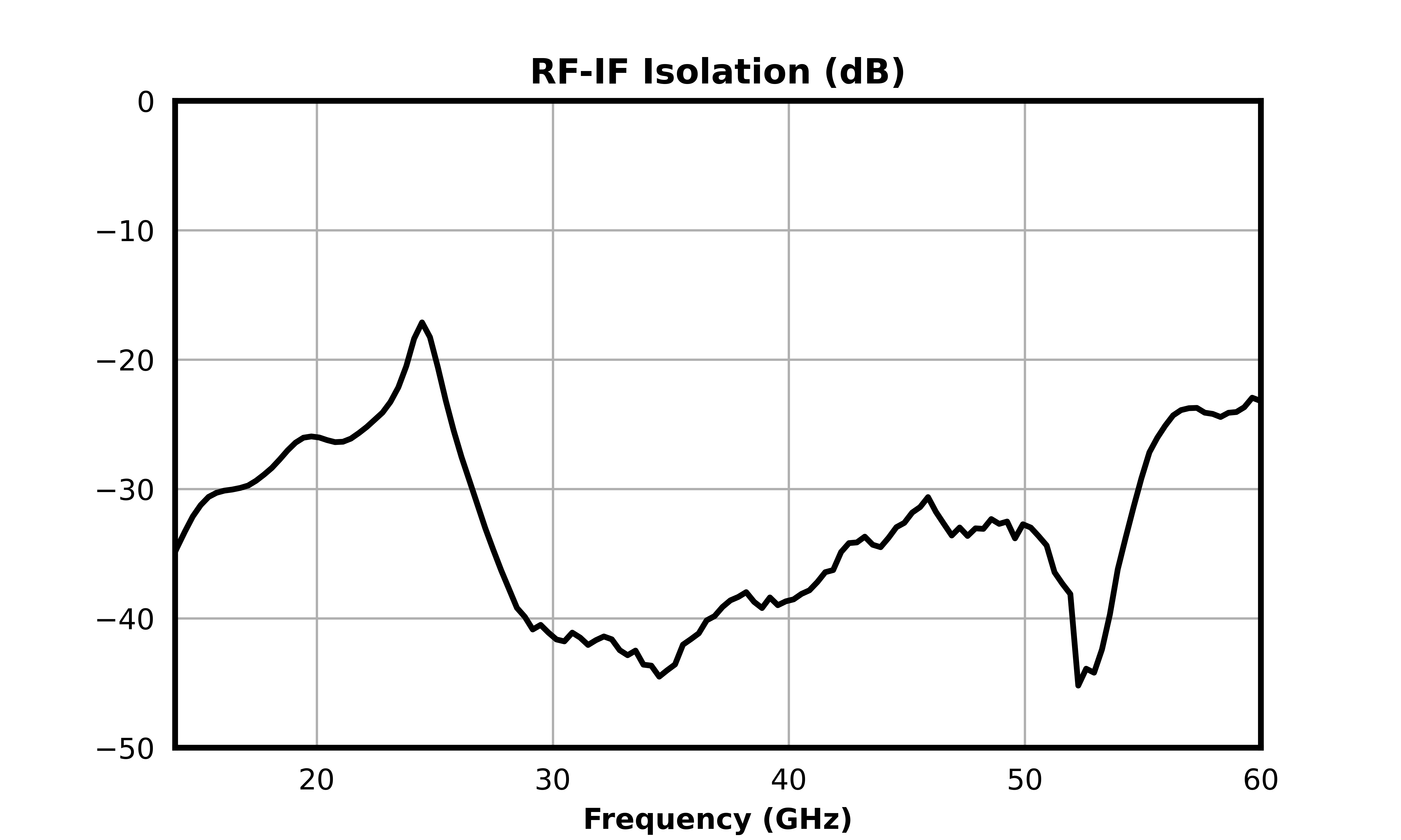
RF-IF Isolation ARF/IF = 18 - 50 GHz
-34-dB

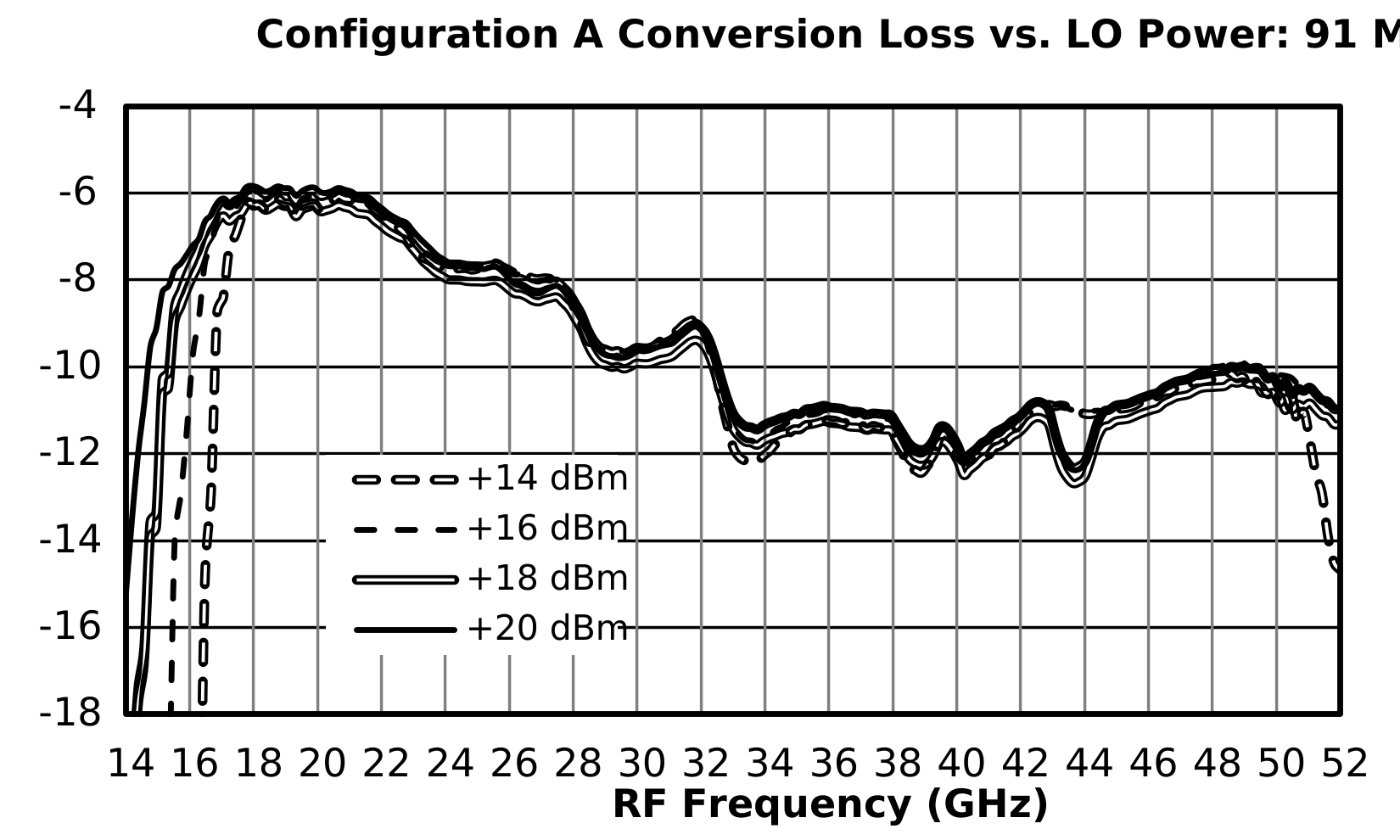
[1] Measured as a down converter to a fixed 91 MHz IF.

[2] Mixer Noise Figure typically measures within 0.5dB of conversion loss for IF frequencies greater than 5 MHz

Rev: - | Copyright © 2026 Marki Microwave LLC.

6

Typical Performance Plot

Conversion Loss (dB) graph for MM1-1850HPSM-2
Input IP3 (dBm) graph for MM1-1850HPSM-2
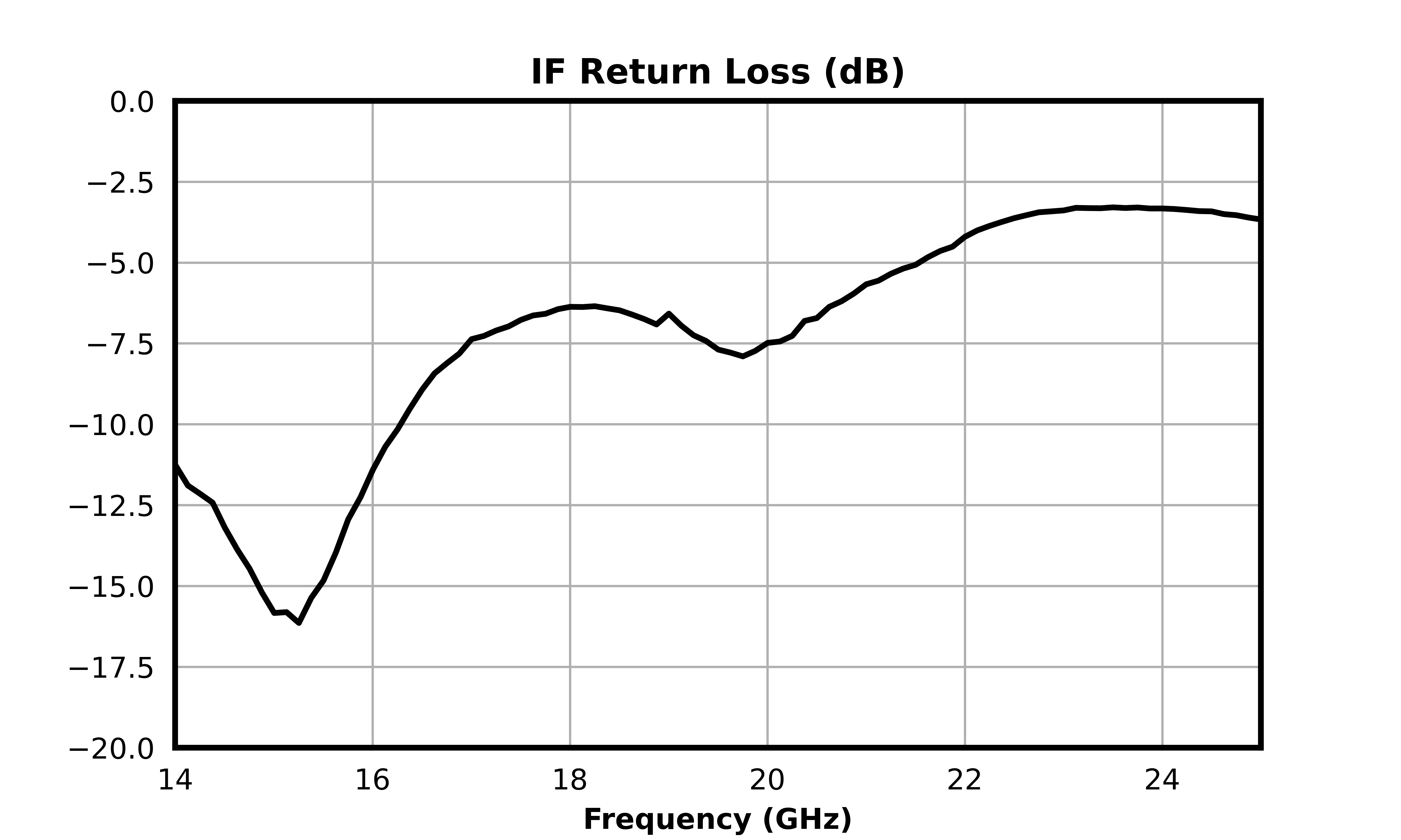
IF Return Loss (dB) graph for MM1-1850HPSM-2
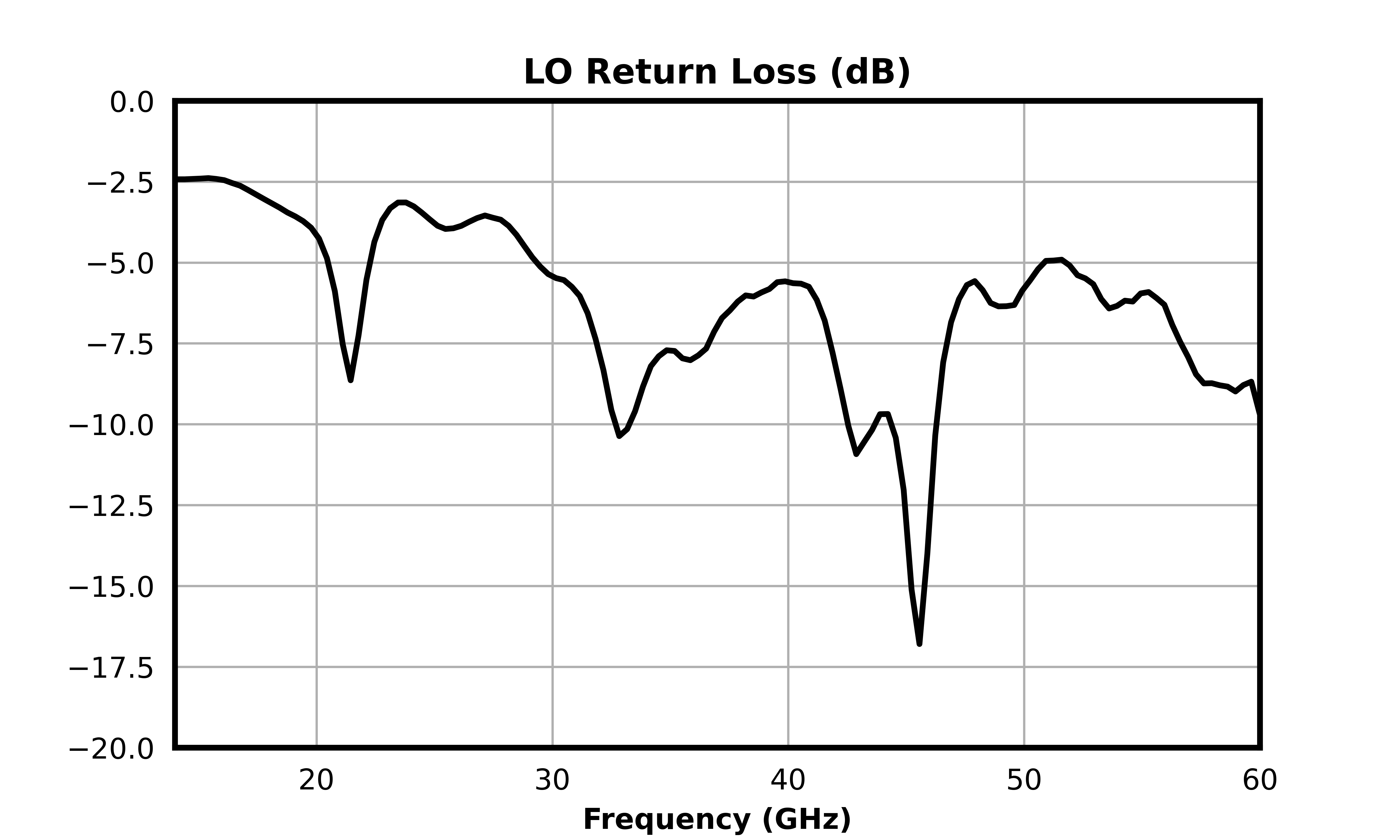
LO Return Loss (dB) graph for MM1-1850HPSM-2
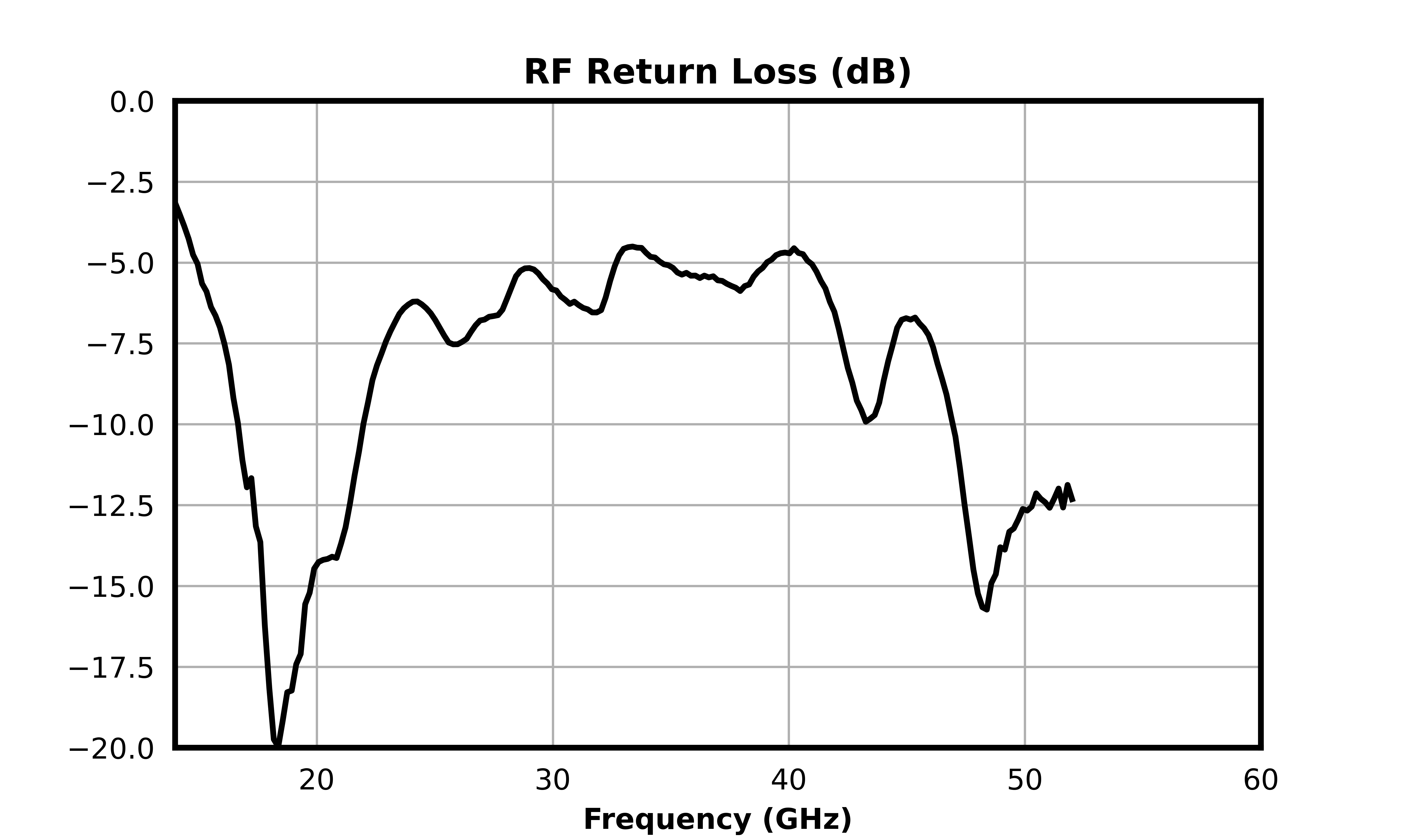
RF Return Loss (dB) graph for MM1-1850HPSM-2
RF-IF Isolation (dB) graph for MM1-1850HPSM-2
LO-RF Isolation (dB) graph for MM1-1850HPSM-2
LO-IF Isolation (dB) graph for MM1-1850HPSM-2

Rev: - | Copyright © 2026 Marki Microwave LLC.

7

Conversion Loss vs LO Power: 91MHz IF (dB)  graph for MM1-1850HPSM-2
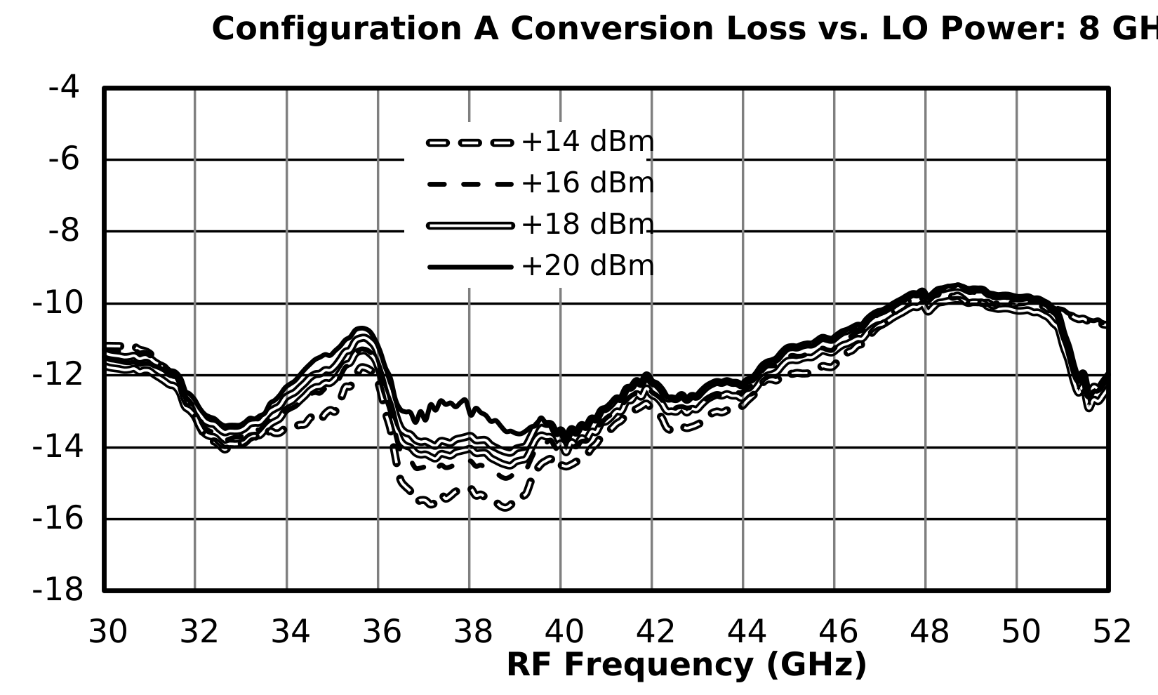
Conversion Loss vs LO Power, 50GHz Fixed LO, 50.1 GHz RF (dB) graph for MM1-1850HPSM-2

Rev: - | Copyright © 2026 Marki Microwave LLC.

8

Typical Performance Plot: LO Harmonic Suppression

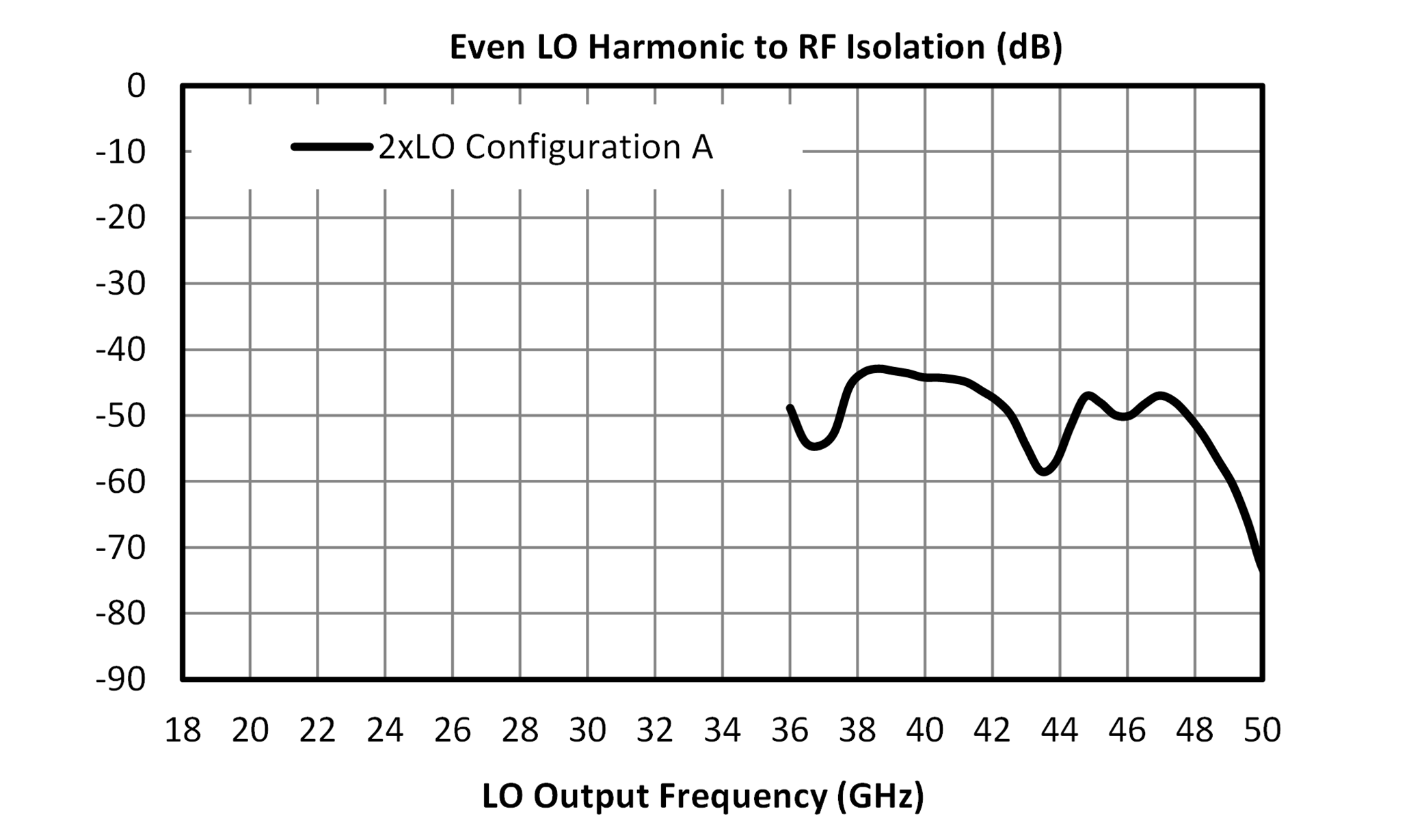
Even LO Harmonic to RF Isolation (dB) graph for MM1-1850HPSM-2
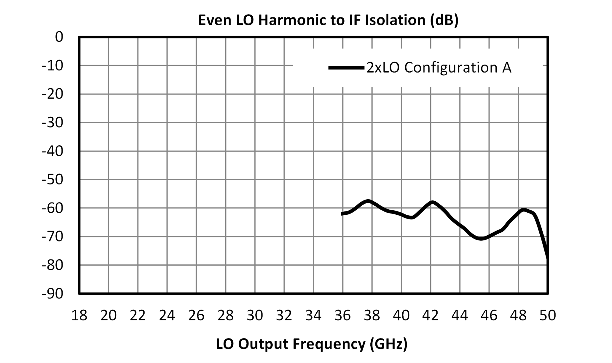
Even LO Harmonic to IF Isolation (dB) graph for MM1-1850HPSM-2
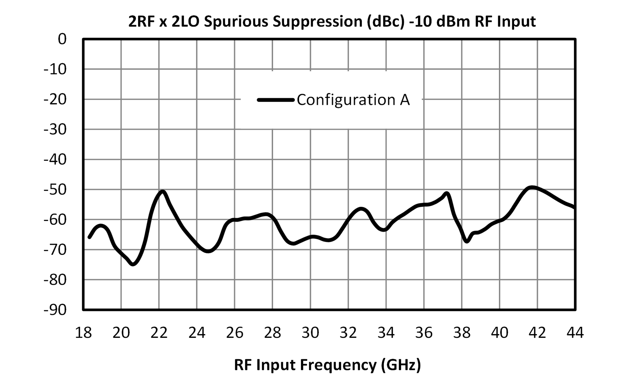
2RF x 2LO Spurious Suppression (dBc) -10 dBm RF Input graph for MM1-1850HPSM-2
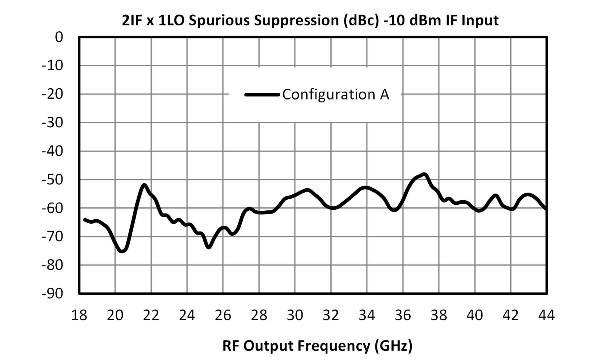
2IF x 1LO Spurious Suppression (dBc) -10 dBm IF input graph for MM1-1850HPSM-2
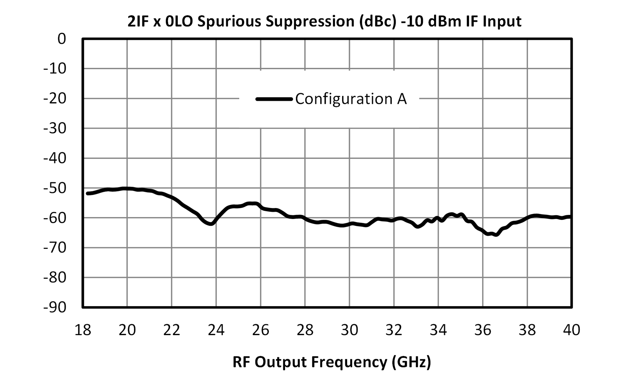
2IF x 0LO Spurious Suppression (dBc) -10 IF Input graph for MM1-1850HPSM-2
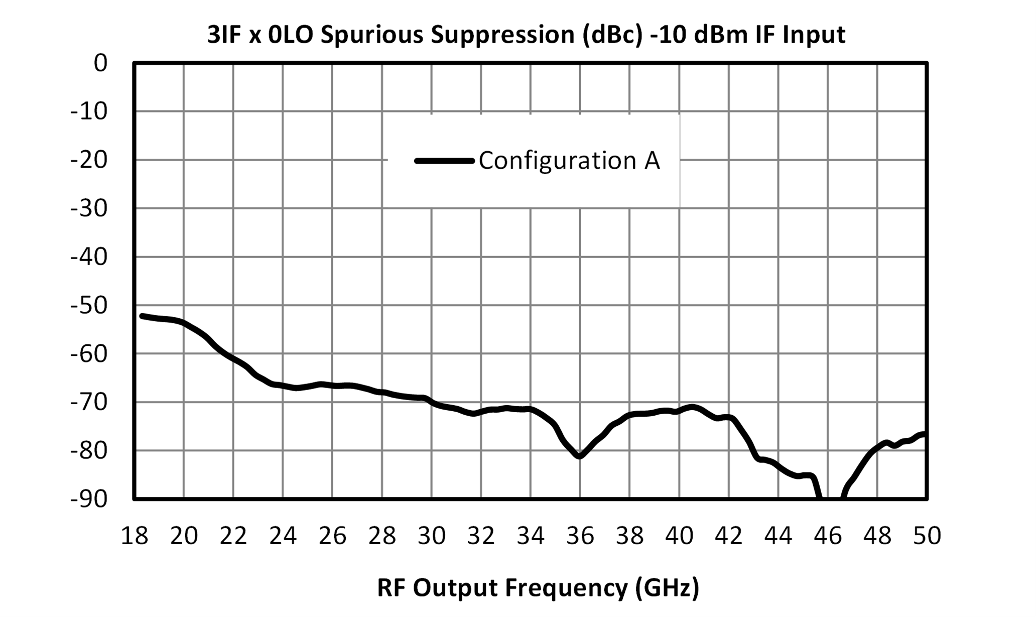
3IF x 0LO Spurious Suppression (dBc) -10 dBm IF Input graph for MM1-1850HPSM-2

Rev: - | Copyright © 2026 Marki Microwave LLC.

9

Application Circuit

Application Circuit for MM1-1850HPSM-2

Rev: - | Copyright © 2026 Marki Microwave LLC.

10

Mechanical Data

Rev: - | Copyright © 2026 Marki Microwave LLC.

11

Rev: - | Copyright © 2026 Marki Microwave LLC.

12

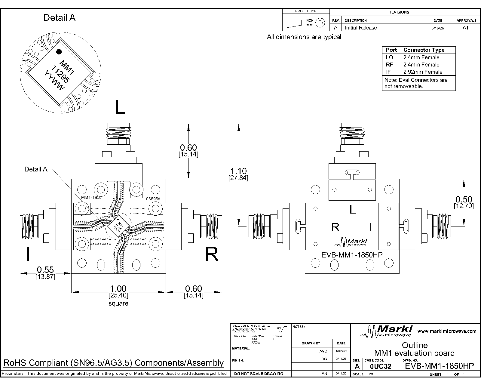
Evaluation Board - Outline Drawing

Outline Drawing

Rev: - | Copyright © 2026 Marki Microwave LLC.

13