Port Diagram
Sales: 408-778-9952 | General: 408-778-4200 | Fax: 408-778-4300
Sales & Customer Support: [email protected]
Tech Support: [email protected]
The FB series bandpass filters are CAD-optimized microstrip filter designs built on a low-loss substrate. These filters feature low insertion loss, excellent return loss and are suitable for high rejection filtering.

| Part Number | Description | Package | Green Status | Product Lifecycle | Export Classification |
|---|---|---|---|---|---|
| FB-1445SM | 14.45 GHz Surface Mount Bandpass Filter | SM | Non-RoHS | Released | EAR99 |
| Part Number | Description | Package | Green Status | Product Lifecycle | Export Classification |
|---|---|---|---|---|---|
| FB-1445SM | 14.45 GHz Surface Mount Bandpass Filter | SM | Non-RoHS | Released | EAR99 |
FB-1445SM
14.45 GHz Surface Mount Bandpass Filter
| Revision Code | Revision Date | Comment |
|---|---|---|
| - | 2016-02-09 | Initial Date Release |
FB-1445SM
14.45 GHz Surface Mount Bandpass Filter
| Port | Function | Description | DC Equivalent Circuit |
|---|---|---|---|
| Port 1 | Input/Output | Port 1 is DC open to Port 2 and GND. GND is provided through the case. |  |
| Port 2 | Input/Output | Port 2 is DC open to Port 1 and GND. GND is provided through the case. | |
FB-1445SM
14.45 GHz Surface Mount Bandpass Filter
| Parameter | Details | Rating |
|---|---|---|
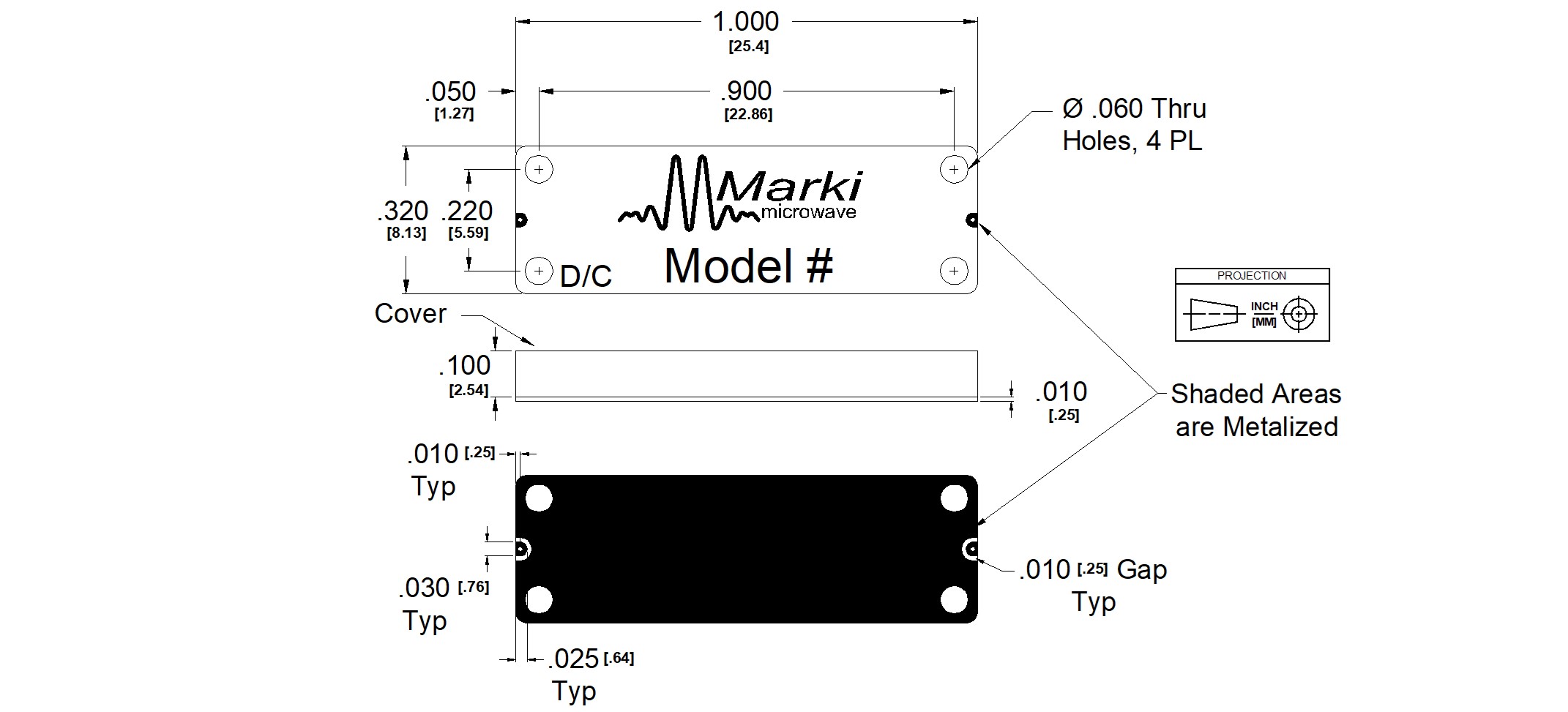
| Dimensions | - | 25.4 x 8.13 mm |
| Moisture Sensitivity Level | - | MSL 3 |
FB-1445SM
14.45 GHz Surface Mount Bandpass Filter
Specifications guaranteed from -55 to +100°C, measured in a 50Ω system.
| Parameter | Test Conditions | Minimum Frequency (GHz) | Maximum Frequency (GHz) | Min | Typ | Max | Unit |
|---|---|---|---|---|---|---|---|
| 1 dBc Passband | Temp = 25°C | 13.22 | 15.71 | - | - | - | GHz |
| 3 dBc Passband | Temp = 25°C | 12.83 | 15.97 | - | - | - | GHz |
| 30 dBc Rejection Point | Temp = 25°C | 10.59 | 17.42 | - | - | - | GHz |
| Center Freq | Temp = 25°C | - | - | - | 14.41 | - | GHz |
| Insertion Loss @ fc | Temp = 25°C | - | - | - | 1.9 | 3.0 | dB |
| Passband Return Loss | Temp = 25°C | - | - | - | 16 | - | dB |
| Group Delay | Temp = 25°C | - | - | - | 463 | - | ps |
| Impedance | Temp = 25°C | - | - | - | 50 | - | Ω |
| RF Power | - | - | - | - | - | 1 | W |
| Stopband Suppression, High Band | 18.0 | 18 | 18 | - | 35 | - | dB |
| Stopband Suppression, High Band | 19.3 | 19.3 | 19.3 | - | 50 | - | dB |
| Stopband Suppression, Low Band | 8.5 | 8.5 | 8.5 | - | 50 | - | dB |
| Stopband Suppression, Low Band | 9.7 | 9.7 | 9.7 | - | 35 | - | dB |
FB-1445SM
14.45 GHz Surface Mount Bandpass Filter

FB-1445SM
14.45 GHz Surface Mount Bandpass Filter
.png)
.png)
.png)
.png)
.png)
FB-1445SM
14.45 GHz Surface Mount Bandpass Filter
FB-1445SM
14.45 GHz Surface Mount Bandpass Filter
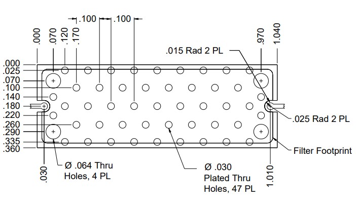
Download : Footprint Drawing