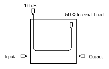
Port Diagram
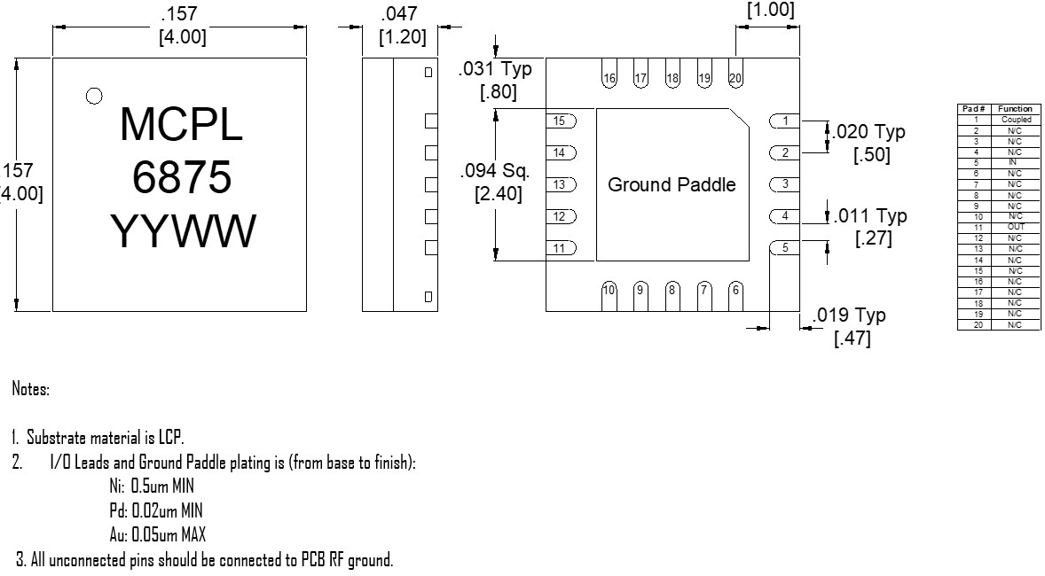
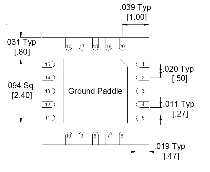
A bottom-up view of the MC16-0222SM’s SM package outline drawing is shown below.
Sales: 408-778-9952 | General: 408-778-4200 | Fax: 408-778-4300
Sales & Customer Support: [email protected]
Tech Support: [email protected]
MC16-0222SM is a MMIC 2-22 GHz Directional Coupler. Passive GaAs MMIC technology allows production of smaller constructions that replace larger form factor circuit board constructions. Tight fabrication tolerances result in less unit to unit variation than traditional coupler technologies, allowing for accurate simulations using the provided S3P file taken from measured production units. The MC16-0222SM is available as a 4 X 4 mm QFN package. Evaluation boards are also available.
N/A
| Part Number | Description | Package | Green Status | Product Lifecycle | Export Classification |
|---|---|---|---|---|---|
| MC16-0222SM | MMIC 2-22 GHz Directional Coupler | QFN | REACH RoHS | Released | EAR99 |
| EVAL-MC16-0222 | Evaluation Board, MMIC 2-22 GHz Directional Coupler | EVAL | REACH RoHS | Released | EAR99 |
MC16-0222SM
MMIC 2-22 GHz Directional Coupler
| Revision Code | Revision Date | Comment |
|---|---|---|
| - | 2020-07-01 | Initial Datasheet Release |
| A | 2020-08-01 | Updated Return Loss Plots |
| B | 2025-02-12 | Updated Power Handling |
| C | 2025-11-21 | Updated ESD Rating |
| D | 2026-06-05 | Corrected Unit of Power Handling Rating |
MC16-0222SM
MMIC 2-22 GHz Directional Coupler
A bottom-up view of the MC16-0222SM’s SM package outline drawing is shown below.
| Port | Function | Description | DC Equivalent Circuit |
|---|---|---|---|
| Pad | Ground | SM package ground path is provided through the ground paddle. |  |
| Pin 1 | Coupled | The coupled port is DC connected to a 50 Ω load. |  |
| Pin 11 | Output | The output port is DC short to the input port and open to ground. | |
| Pin 5 | Input | The input port is DC short to the output port and open to ground. | |
MC16-0222SM
MMIC 2-22 GHz Directional Coupler
The Absolute Maximum Ratings indicate limits beyond which damage may occur to the device. If these limits are exceeded, the device may be inoperable or have a reduced lifetime.
| Parameter | Maximum Rating | Unit |
|---|---|---|
| DC Current at any Port | 60 | mA |
| Maximum Operating Temperature | 100 | °C |
| Maximum Storage Temperature | 125 | °C |
| Minimum Operating Temperature | -55 | °C |
| Minimum Storage Temperature | -65 | °C |
| RF Power Handling | 30 | dBm |
| Parameter | Details | Rating |
|---|---|---|
| ESD | 250 to < 500 Volts | HBM Class 1A |
| Dimensions | - | 4 x 4 mm |
| Moisture Sensitivity Level | - | MSL 1 |
MC16-0222SM
MMIC 2-22 GHz Directional Coupler
The electrical specifications apply at TA=+25°C in a 50Ω system. Min and Max limits are guaranteed at TA=+25°C. All measured data is taken from the eval board with de-embedding of the connectors and traces, but group delay may vary.
| Parameter | Test Conditions | Minimum Frequency (GHz) | Maximum Frequency (GHz) | Min | Typ | Max | Unit |
|---|---|---|---|---|---|---|---|
| Directivity | - | 12 | 22 | - | 15 | - | dB |
| Directivity | - | 2 | 12 | 14 | 23 | - | dB |
| Direct Line Insertion Loss | DC-12 | - | - | - | 1.2 | 2.5 | dB |
| Direct Line Insertion Loss | - | 12 | 22 | - | 2 | 3.5 | dB |
| Impedance | - | - | - | - | 50 | - | Ω |
| Mean Coupling | - | 2 | 22 | - | 16 | - | dB |
| VSWR | - | 2 | 22 | - | 1.22 | - | - |
MC16-0222SM
MMIC 2-22 GHz Directional Coupler
All measured data is taken from the eval board with de-embedding of the connectors and traces, but group delay may vary.


MC16-0222SM
MMIC 2-22 GHz Directional Coupler
MC16-0222SM
MMIC 2-22 GHz Directional Coupler
Download : Footprint Drawing

MC16-0222SM
MMIC 2-22 GHz Directional Coupler