Port Diagram

Sales: 408-778-9952 | General: 408-778-4200 | Fax: 408-778-4300
Sales & Customer Support: [email protected]
Tech Support: [email protected]
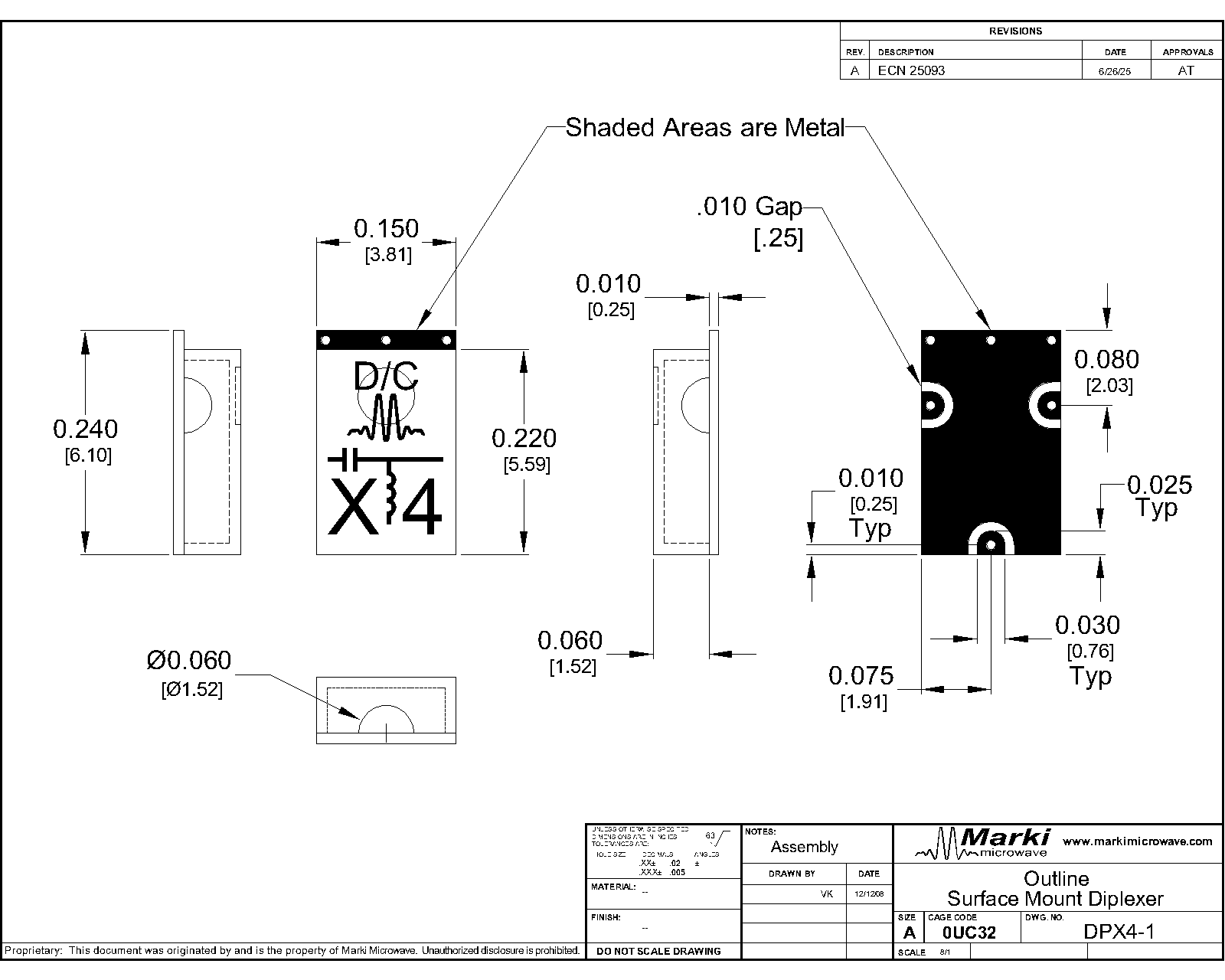
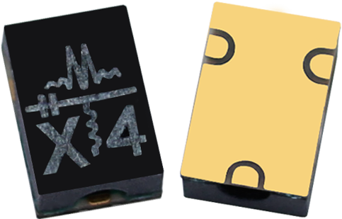
Available in either a connectorized or miniature surface mount package (0.240 inch x 0.150 inch), the DPX-4 is a low cost, high performance diplexer. The unique design offers high pass/low pass signal routing/multiplexing with excellent isolation. Passband insertion loss is less than 1.4 dB with rejection typically exceeding 25 dB. Besides being ideal for transmitter/receiver applications, the DPX-4 can also be used as an excellent non-reflective low pass (or high pass) filter for systems requiring broadband 50Ω impedance match (such as mixers).

| Part Number | Description | Package | Green Status | Product Lifecycle | Export Classification |
|---|---|---|---|---|---|
| DPX-4-1 | Diplexer | DPX | RoHS REACH | Released | EAR99 |
| DPX-4-2 | Diplexer | DPX | RoHS REACH | Released | EAR99 |
| Part Number | Description | Package | Green Status | Product Lifecycle | Export Classification |
|---|---|---|---|---|---|
| DPX-4-1 | Diplexer | DPX | RoHS REACH | Released | EAR99 |
| DPX-4-2 | Diplexer | DPX | RoHS REACH | Released | EAR99 |
DPX-4-1
Diplexer
| Revision Code | Revision Date | Comment |
|---|---|---|
| - | 2012-10-18 | Datasheet Initial Release |
DPX-4-1
Diplexer
| Port | Function | Description | DC Equivalent Circuit |
|---|---|---|---|
| GND | Ground | DPX package ground is provided through the substrate and ground bond pads. |  |
| Pin 1 | RF High Band | Pin 1 is DC open to Pin 2 and Pin 3. |  |
| Pin 2 | Common/Input | Pin 2 is DC open to Pin 1 and short to Pin 3. |  |
| Pin 3 | RF Low Band | Pin 3 is DC open to Pin 1 and short to Pin 2. | |
DPX-4-1
Diplexer
| Parameter | Details | Rating |
|---|---|---|
| Weight | Package name: DPX | 0.05g |
| Dimensions | - | 3.81 x 6.10 mm |
| Moisture Sensitivity Level | - | MSL 3 |
DPX-4-1
Diplexer
Specifications guaranteed from -55 to +100°C, measured in a 50Ω system.
| Parameter | Test Conditions | Minimum Frequency (GHz) | Maximum Frequency (GHz) | Min | Typ | Max | Unit |
|---|---|---|---|---|---|---|---|
| 30 dBc Low Pass Rejection Point | <2.8 GHz | - | 2.8 | - | 25 | - | dB |
| 30 dBc Low Pass Rejection Point | <2 GHz | - | 2 | 30 | 40 | - | dB |
| Common Port Return Loss | <2.8 GHz | - | 2.8 | - | 12 | - | dB |
| Common Port Return Loss | 5.5-12 GHz | 5.5 | 12 | - | 12 | - | dB |
| Cross Over Frequency | 4.1 GHz | 4.1 | 4.1 | - | 5 | - | % |
| High Pass Filter, Pass Band Insertion Loss | 5.5-12 GHz | 5.5 | 12 | - | 1.2 | 2.4 | dB |
| High Pass Filter, Pass Band Return Loss | 5.5-12 GHz | 5.5 | 12 | - | 12 | - | dB |
| Isolation | <2.8 GHz | - | 2.8 | 20 | 30 | - | dB |
| Isolation | 5.5-12 GHz | 5.5 | 12 | 15 | 25 | - | dB |
| Low Pass Filter, Pass Band Insertion Loss | 0-2.8 GHz | 0 | 2.8 | - | 0.8 | 1.6 | dB |
| Low Pass Filter, Pass Band Return Loss | <2.7 GHz | - | 2.7 | - | 12 | - | dB |
| Low Pass Filter, Stop Band Rejection | 5.5-6 GHz | 5.5 | 6 | - | 20 | - | dB |
| Low Pass Filter, Stop Band Rejection | 6-12 GHz | 6 | 12 | 15 | 25 | - | dB |
| RF Power | - | - | - | - | - | 1 | W |
| 1 dBc High Passband | - | - | - | 5.5 | - | 12 | GHz |
| 1 dBc Low Passband | - | - | - | 0 | - | 2.8 | GHz |
DPX-4-1
Diplexer


DPX-4-1
Diplexer
DPX-4-1
Diplexer
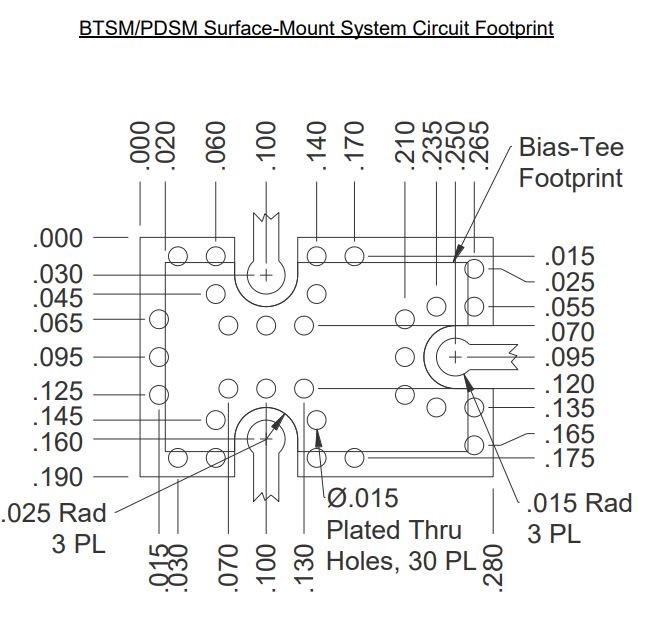
Download : Footprint Drawing