Port Diagram
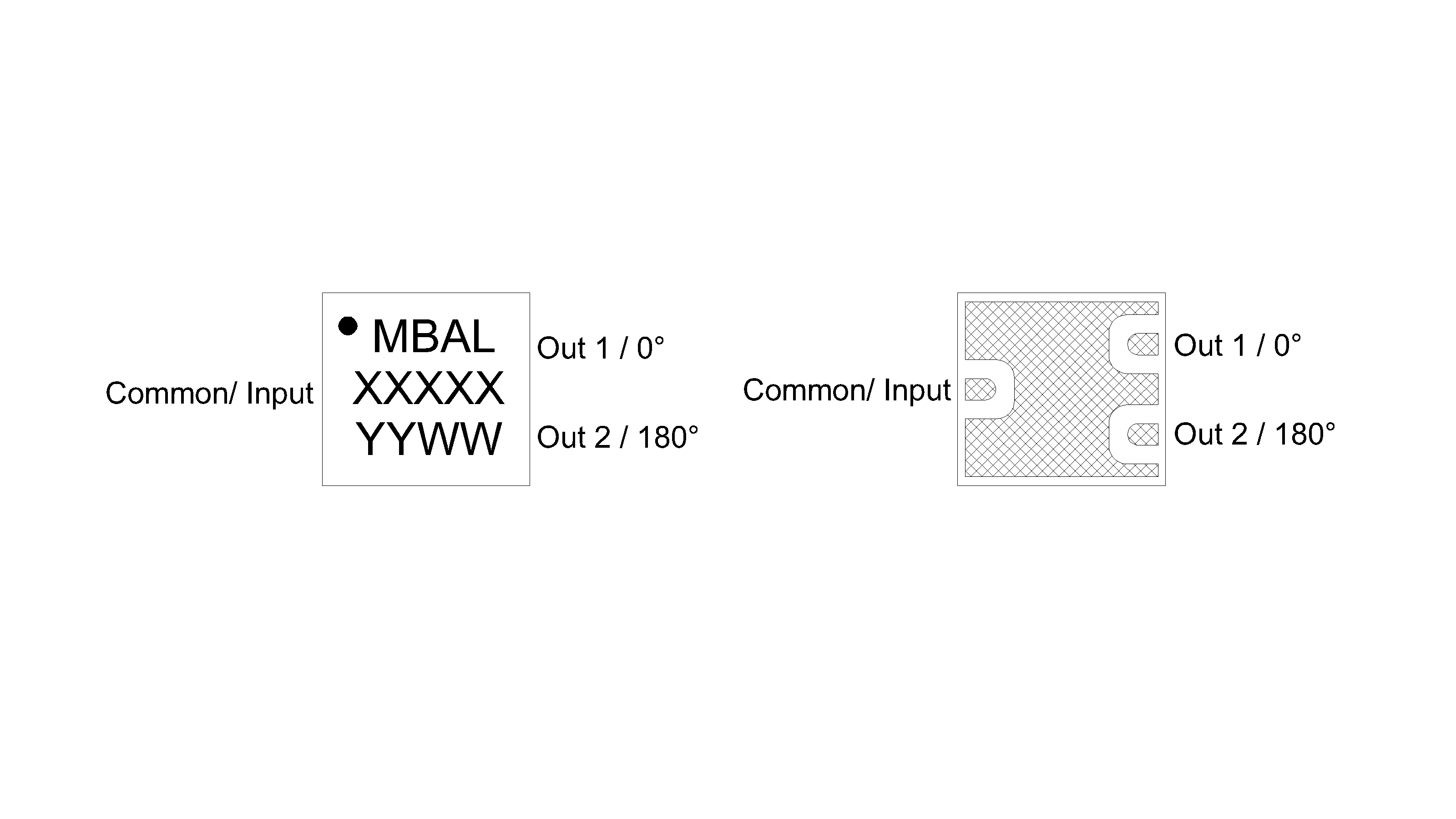
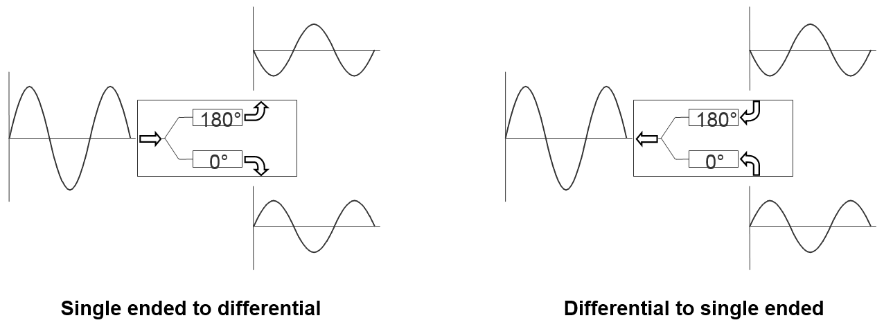
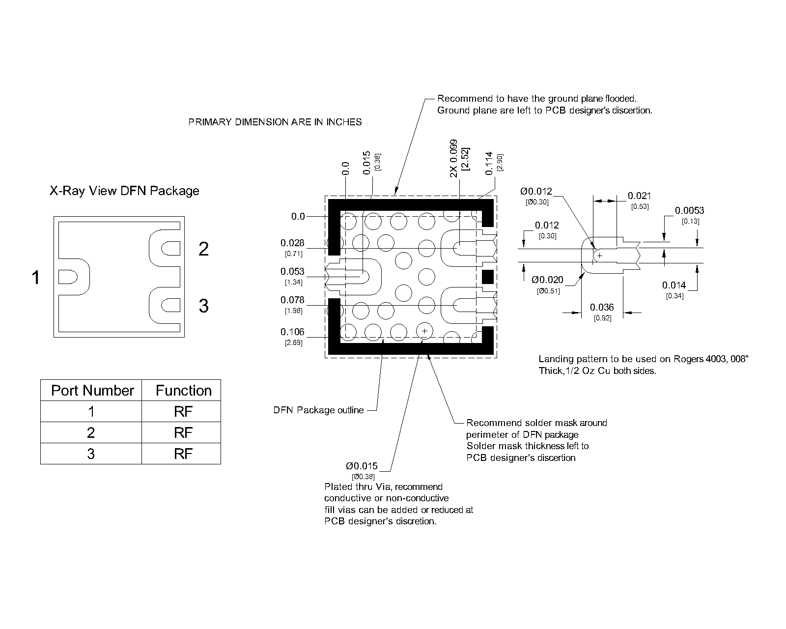
An X-ray top-down view of the MBAL-0620SMG package outline drawing is shown below. The MMIC Baluns are passive reciprocal devices allowing either signal splitting or combining.
Sales: 408-778-9952 | General: 408-778-4200 | Fax: 408-778-4300
Sales & Customer Support: [email protected]
Tech Support: [email protected]
The MBAL-0620SMG is a MMIC surface mount high isolation balun. This balun features excellent amplitude and phase balance across its 6 to 20 GHz frequency range and offers a 2:1 impedance ratio. It provides 18 typical isolation between the balanced ports, minimizing unwanted signal coupling. The balun also suppresses common-mode signals, helping maintain signal integrity in differential applications. The MBAL-0620SMG is form-fit compatible with the BAL-0620SMG and is intended for customers supporting existing designs. For new designs, we recommend the MBAL-0624PSM, which offers improved performance in a compact 1.3 x 2mm DFN package.

| Part Number | Description | Package | Green Status | Product Lifecycle | Export Classification |
|---|---|---|---|---|---|
| MBAL-0620SMG | 6 - 20 GHz MMIC Isolation Balun | DFN | REACH RoHS | Released | EAR99 |
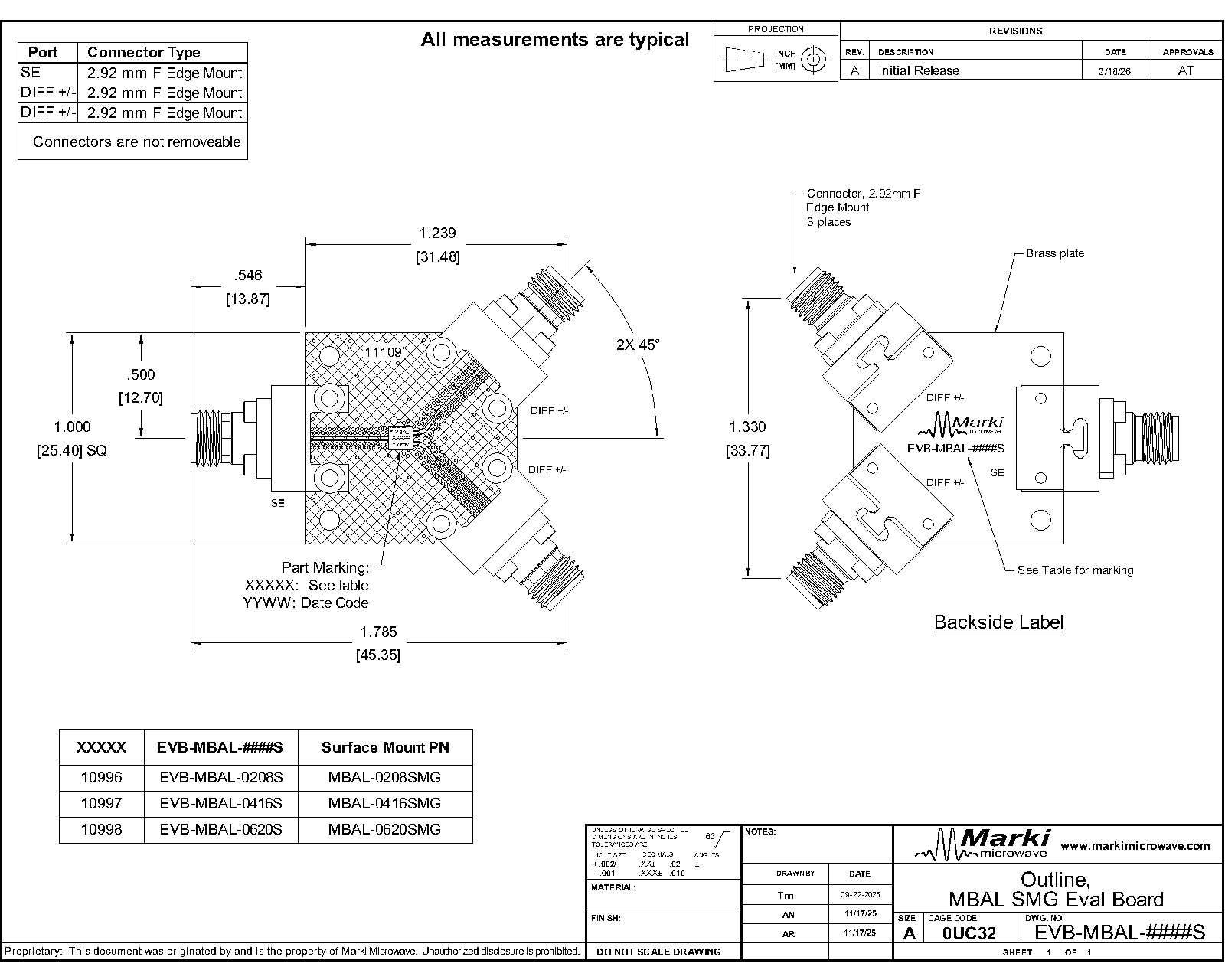
| EVB-MBAL-0620S | Evaluation Board, 6 - 20 GHz MMIC Isolation Balun | EVB | REACH RoHS | Released | EAR99 |
| Part Number | Description | Package | Green Status | Product Lifecycle | Export Classification |
|---|---|---|---|---|---|
| MBAL-0620SMG | 6 - 20 GHz MMIC Isolation Balun | DFN | REACH RoHS | Released | EAR99 |
| EVB-MBAL-0620S | Evaluation Board, 6 - 20 GHz MMIC Isolation Balun | EVB | REACH RoHS | Released | EAR99 |
MBAL-0620SMG
6 - 20 GHz MMIC Isolation Balun
| Revision Code | Revision Date | Comment |
|---|---|---|
| - | 2026-03-27 | Initial Release |
| A | 2026-06-02 | Added min/max limit specs |
MBAL-0620SMG
6 - 20 GHz MMIC Isolation Balun
An X-ray top-down view of the MBAL-0620SMG package outline drawing is shown below. The MMIC Baluns are passive reciprocal devices allowing either signal splitting or combining.
| Port | Function | Description | DC Equivalent Circuit |
|---|---|---|---|
| Ground Paddle | Gnd | Ground paddle should be connected to RF ground |  |
| Pin 1 | Common/Input | Pin 1 is DC open. |  |
| Pin 2 | Out 1 / 0° Port (Balanced) | Pin 2 is DC short to ground. |  |
| Pin 3 | Out 2 / 180° Port (Balanced) | Pin 3 is DC short to ground. | |
MBAL-0620SMG
6 - 20 GHz MMIC Isolation Balun
The Absolute Maximum Ratings indicate limits beyond which damage may occur to the device. If these limits are exceeded, the device may be inoperable or have a reduced lifetime.
| Parameter | Maximum Rating | Unit |
|---|---|---|
| Maximum Operating Temperature | 100 | °C |
| Maximum Storage Temperature | 125 | °C |
| Minimum Operating Temperature | -55 | °C |
| Minimum Storage Temperature | -65 | °C |
| Pin 2 DC Current | 24 | mA |
| Pin 3 DC Current | 24 | mA |
| Parameter | Details | Rating |
|---|---|---|
| ESD | 250 to < 500 Volts | HBM Class 1A |
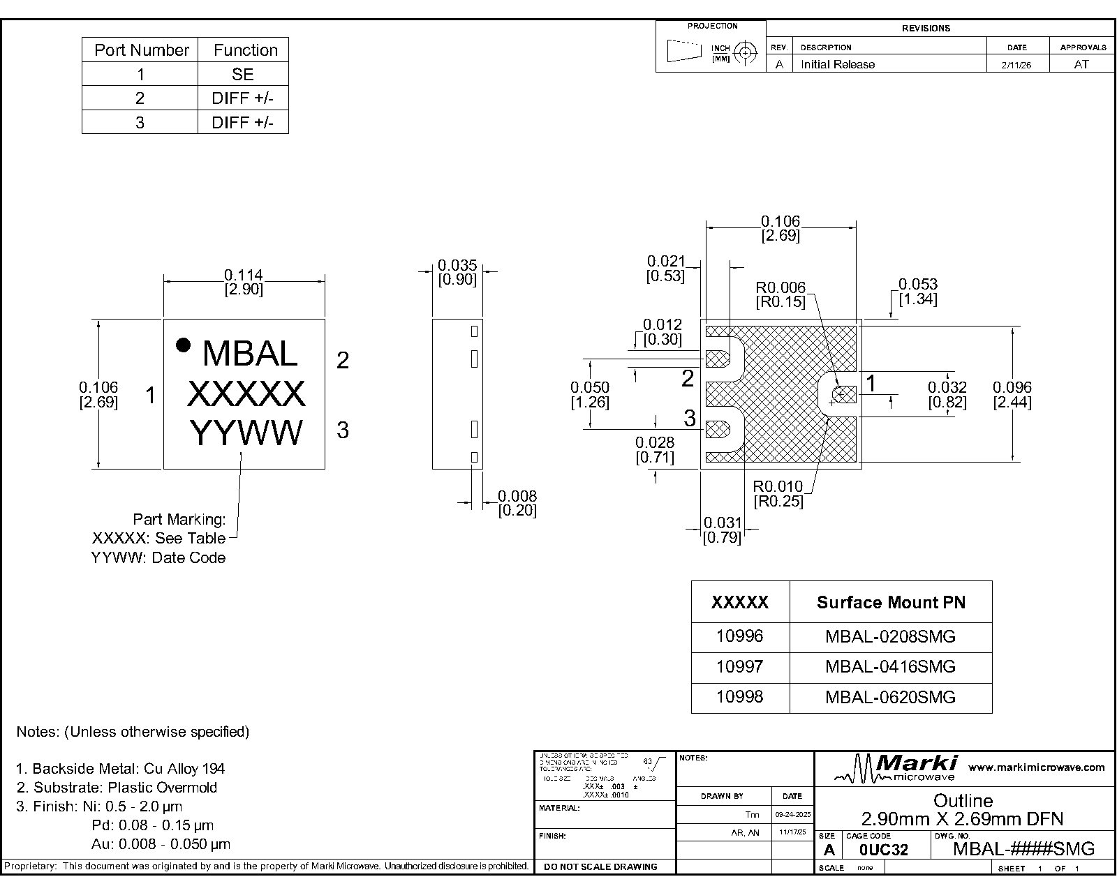
| Dimensions | - | 2.69 x 2.90 mm |
| Moisture Sensitivity Level | - | MSL 1 |
MBAL-0620SMG
6 - 20 GHz MMIC Isolation Balun
The electrical specifications apply at TA=+25°C in a 50Ω system. Min and Max limits are guaranteed at TA=+25°C.
| Parameter | Test Conditions | Minimum Frequency (GHz) | Maximum Frequency (GHz) | Min | Typ | Max | Unit |
|---|---|---|---|---|---|---|---|
| Nominal Phase Shift | Temp = 25°C | - | - | - | 180 | - | ° |
| Insertion Loss as a Mode Converter | Temp = 25°C | 6 | 20 | - | 1.7 | 4.2 | dB |
| Common Port Return Loss | Temp = 25°C | 6 | 20 | - | 15 | - | dB |
| Unbalanced Port Return Loss | Temp = 25°C | 6 | 20 | - | 14.9 | - | dB |
| Common Mode Return Loss | Temp = 25°C | 6 | 20 | - | 11 | - | dB |
| Output Return Loss | Temp = 25°C | 6 | 20 | - | 13 | - | dB |
| Isolation | Temp = 25°C | 6 | 20 | - | 18 | - | dB |
| Amplitude Balance | Temp = 25°C | 6 | 20 | - | 0.2 | 1.0 | dB |
| Phase Balance | Temp = 25°C | 6 | 20 | - | 3.2 | 12.0 | ° |
| Common Mode Rejection | Temp = 25°C | 6 | 16 | 25 | 28 | - | dB |
| Common Mode Rejection | - | 16 | 20 | 21 | 26 | - | dB |
| Impedance | Temp = 25°C | - | - | - | 50 | - | Ω |
| Impedance Ratio | - | 6 | 20 | - | 2:1 | - | - |
MBAL-0620SMG
6 - 20 GHz MMIC Isolation Balun
.png)
.png)
.png)
.png)
.png)
.png)
MBAL-0620SMG
6 - 20 GHz MMIC Isolation Balun
.png)
.png)
.png)
.png)
.png)
.png)
Measured data is de-embedded from fixture using AFR.
MBAL-0620SMG
6 - 20 GHz MMIC Isolation Balun
MBAL-0620SMG
6 - 20 GHz MMIC Isolation Balun
Download : Footprint Drawing
MBAL-0620SMG
6 - 20 GHz MMIC Isolation Balun