Rev: - | Copyright © 2020 Marki Microwave LLC.

General Description

The BALH-0012SSG is a broadband surface mount balun, hand-tuned for optimal phase and amplitude balance over a 10 MHz to 12 GHz bandwidth. It serves as an excellent choice for analog to digital converters, balanced receivers, baseband digital modulations, and signal integrity enhancement.

Features

  • 1:1 Impedance Ratio
  • 10 MHz to 12 GHz Balun (Balanced to Unbalanced Transformer)
  • High 37 dBm 1-dB compression enables high power applications
  • Tuned for Optimal Phase/Amplitude Balance

Functional Block Diagram

Block Diagram
Photo of BALH-0012SSG

Electrical Performance Summary

ParameterTypUnit
Frequency Range0.01 to 12GHz
Insertion Loss as a Mode Converter 2dB
Phase Balance 5°
Amplitude Balance 0.6dB
Impedance Ratio 1:1-
Common Mode Rejection 25dB

Summary only – refer to the Electrical Specifications, Absolute Maximum Ratings, and Recommended Operating Range tables for complete details.

Part Ordering Options

Part NumberDescriptionPackageGreen StatusProduct LifecycleExport Classification
BALH-0012SSGHIGH POWER SURFACE-MOUNT BALUNSSG

REACH

RoHS

ReleasedEAR99
EVAL-BALH-0012Evaluation Board, High Power Surface-Mount BalunEVAL

REACH

RoHS

ReleasedEAR99

Table Of Contents

Mixed Mode Scattering Parameters

Mixed mode scattering parameters are used to characterize differential circuits. For baluns, this means that the 0° and 180° ports become a single differential port and the common port remains common port. The two-port s-parameters of the balun are then characterized based on differential (d), common mode (c), or single-ended (s) signals. For example: Sds12 is the differential output response given a single ended input.

Insertion loss as a mode converter graph for BALH-0012SSG
Insertion loss as a mode converter, 50 units spread graph for BALH-0012SSG
Differential port return loss graph for BALH-0012SSG
Insertion loss of a common mode signal graph for BALH-0012SSG
Reflection converted between differential and common modes graph for BALH-0012SSG
Return loss of a common mode signal graph for BALH-0012SSG
Unbalanced port return loss graph for BALH-0012SSG

Typical Performance Scattering Parameter

Three port scattering parameters measured as three single-ended 50Ω ports showing relationship between any two ports.

Common to output port insertion loss graph for BALH-0012SSG
Return loss for common port and output ports graph for BALH-0012SSG
Common mode rejection graph for BALH-0012SSG
Common Mode Rejection, 50 Units Spread graph for BALH-0012SSG
Amplitude balance between output ports graph for BALH-0012SSG
Amplitude Balance Between Output Ports, 50 Unit Spread graph for BALH-0012SSG
Phase balance between output ports graph for BALH-0012SSG
Phase Balance Between Output Ports, 50 Unit Spread graph for BALH-0012SSG
Isolation between output ports graph for BALH-0012SSG
Low Frequency Insertion Loss (dB) graph for BALH-0012SSG

Specifications

Electrical Specifications

The electrical specifications apply at TA=+25°C in a 50Ω system. Min and Max limits are guaranteed at TA=+25°C.

ParameterTest ConditionsMinimum
Frequency
(GHz)
Maximum
Frequency
(GHz)
MinTypMaxUnit
Frequency Range-0.01 12---GHz
Amplitude Balance -0.01 12-0.61.8dB
Common Mode Rejection -0.01 121625-dB
Input P1dB -0.01 12-37-dBm
Insertion Loss as a Mode Converter -0.01 12-23.5dB
Isolation -0.01 12-6-dB
Nominal Phase Shift -0.01 12-180-°
Phase Balance -0.01 12-512°
VSWR (Common) -0.01 12-1.7--
VSWR (Output) -0.01 12-1.35--
Impedance Ratio -- --1:1--

Absolute Maximum Ratings

ParameterMaximum RatingUnit
Maximum Operating Temperature 100°C
Maximum Storage Temperature 125°C
Minimum Operating Temperature -55°C
Minimum Storage Temperature -65°C
RF Power Handling 33dBm

Package Information

ParameterDetailsRating
Dimensions-4.83 x 6.10 mm
Moisture Sensitivity Level-MSL 1

Port Configuration and Functions

Port Functions

PortFunctionDescriptionDC Equivalent
Circuit
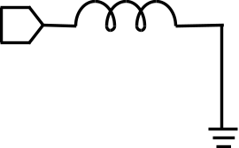
Common Port / In (Unbalanced)RF Input The common port is DC short to ground.Equivalent circuit for the RF Input
Out 1 / 0° Port (Balanced)0° Port The 0° port is DC short to ground.Equivalent circuit for the 0° Port
Out 2 / 180° Port (Balanced)180° Port The 180° port is DC short to ground.Equivalent circuit for the 180° Port

Mechanical Data

Outline Drawing

Download : Outline 2D Drawing Outline 3D Drawing Outline 3D STP

Outline Drawing

Evaluation Board

Evaluation Board - Electrical Specification

ParameterTest ConditionsMinimum
Frequency
(GHz)
Maximum
Frequency
(GHz)
MinTypMaxUnit
Frequency Range-- ----GHz
Impedance Ratio -- --1:1--

Evaluation Board - Outline Drawing

Outline Drawing

Revision History

Revision CodeRevision DateComment
-2020-08-01Draft

DISCLAIMER

MARKI MICROWAVE, LLC., (“MARKI”) PROVIDES TECHNICAL SPECIFICATIONS AND DATA (INCLUDING DATASHEETS), APPLICATION OR OTHER DESIGN ADVICE, WEB TOOLS, AND OTHER INFORMATION AND RESOURCES “AS IS” AND WITH ALL FAULTS. MARKI DISCLAIMS ALL WARRANTIES, EXPRESS OR IMPLIED, INCLUDING, WITHOUT LIMITATION, ANY IMPLIED WARRANTIES OF MERCHANTABILITY, FITNESS FOR A PARTICULAR PURPOSE, OR NON-INFRINGEMENT.

These resources are intended for developers skilled in the art designing with Marki products. You are solely responsible for (1) selecting the appropriate products for your application, (2) designing, validating, and testing your application, and (3) ensuring your application meets applicable standards and other requirements. Marki makes no guarantee regarding the suitability of its products for any particular purpose, nor does Marki assume any liability whatsoever arising out of your use or application of any Marki product.

Marki grants you permission to use these resources only for development of an application that uses Marki products. Other reproduction or use of these resources is strictly prohibited. No license is granted to any other Marki intellectual property or to any third-party intellectual property. Marki reserves the right to make changes to the product(s) or information contained herein without notice.

MARKI MICROWAVE, M wave logo, FastSwitch, and T3 MIXER are trademarks or registered trademarks of Marki Microwave, LLC. All other trademarks used are the property of their respective owners.

© 2020, Marki Microwave, LLC