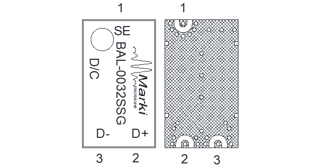
Port Diagram
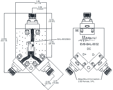
A top-down view of the BAL-0032SSG package outline drawing is shown below. Marki baluns are passive reciprocal devices allowing either single ended to differential or differential to single ended conversion.
Sales: 408-778-9952 | General: 408-778-4200 | Fax: 408-778-4300
Sales & Customer Support: [email protected]
Tech Support: [email protected]
The BAL-0032SSG is a surface-mount broadband balun, hand-tuned for optimal phase and amplitude balance over an industry leading 10 MHz to 32 GHz bandwidth. The BAL-0032SSG operates as an excellent choice for analog to digital converters, balanced receivers, baseband digital modulations, and signal integrity.

| Part Number | Description | Package | Green Status | Product Lifecycle | Export Classification |
|---|---|---|---|---|---|
| BAL-0032SSG | SURFACE-MOUNT BROADBAND BALUN | SSG | REACH RoHS | Released | EAR99 |
| EVB-BAL-0032 | Evaluation Board, 0.01 - 32 GHz Surface-Mount Broadband Balun | EVB | REACH RoHS | Released | EAR99 |
BAL-0032SSG
SURFACE-MOUNT BROADBAND BALUN
| Revision Code | Revision Date | Comment |
|---|---|---|
| - | 2022-06-01 | Datasheet Initial Release |
| A | 2023-01-01 | Unit Spread Graphs Added |
| B | 2025-05-19 | 3D model / footprint updated |
| C | 2026-01-09 | Power Handling Added |
BAL-0032SSG
SURFACE-MOUNT BROADBAND BALUN
A top-down view of the BAL-0032SSG package outline drawing is shown below. Marki baluns are passive reciprocal devices allowing either single ended to differential or differential to single ended conversion.
| Port | Function | Description | DC Equivalent Circuit |
|---|---|---|---|
| Port 1 | Common Port / SE (Unbalanced) | The common port is DC short to ground. |  |
| Port 2 | D+ / 0° Port (Balanced) | The 0° port is DC short to ground. |  |
| Port 3 | D- / 180° Port (Balanced) | The 180° port is DC short to ground. |  |
BAL-0032SSG
SURFACE-MOUNT BROADBAND BALUN
The Absolute Maximum Ratings indicate limits beyond which damage may occur to the device. Absolute Maximum Ratings are individual and should not be met in parallel. If these limits are exceeded, the device may be inoperable or have a reduced lifetime.
| Parameter | Maximum Rating | Unit |
|---|---|---|
| Maximum Operating Temperature | 100 | °C |
| Maximum Storage Temperature | 125 | °C |
| Minimum Operating Temperature | -55 | °C |
| Minimum Storage Temperature | -65 | °C |
| RF Power Handling 1 | 15 | W |
[1] Tested at 6GHz
| Parameter | Details | Rating |
|---|---|---|
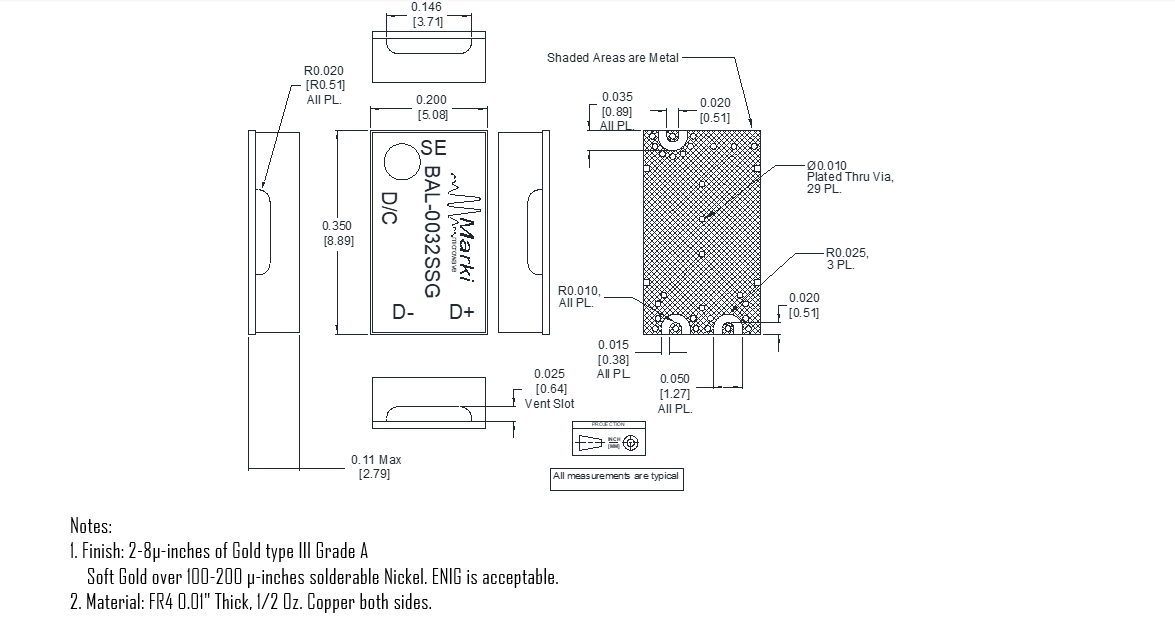
| Dimensions | - | 5.08 x 8.89 mm |
| Moisture Sensitivity Level | - | MSL 1 |
BAL-0032SSG
SURFACE-MOUNT BROADBAND BALUN
The electrical specifications apply at TA=+25°C in a 50Ω system. Min and Max limits are guaranteed at TA=+25°C.
| Parameter | Test Conditions | Minimum Frequency (GHz) | Maximum Frequency (GHz) | Min | Typ | Max | Unit |
|---|---|---|---|---|---|---|---|
| Amplitude Balance | - | 0.1 | 20 | - | 0.5 | 1.3 | dB |
| Amplitude Balance | - | 20 | 32 | - | 0.5 | 1.5 | dB |
| Common Mode Rejection | - | 20 | 32 | - | 25 | 18 | dB |
| Common Mode Rejection | - | 0.1 | 20 | - | 25 | 22 | dB |
| Common Port Return Loss | - | 0.1 | 32 | - | 8 | - | dB |
| Impedance | - | - | - | - | 50 | - | Ω |
| Impedance Ratio | - | - | - | - | 2:1 | - | - |
| Insertion Loss as a Mode Converter | - | 0.01 | 32 | - | 5 | 8 | dB |
| Isolation | - | 0.01 | 32 | - | 8 | - | dB |
| Nominal Phase Shift | - | 0.1 | 32 | - | 180 | - | ° |
| Output Return Loss | - | 0.01 | 32 | - | 9 | - | dB |
| Phase Balance | - | 20 | 32 | - | 5 | 13 | ° |
| Phase Balance | - | 0.01 | 20 | - | 5 | 10 | ° |
BAL-0032SSG
SURFACE-MOUNT BROADBAND BALUN
Mixed mode scattering parameters are used to characterize differential circuits. For baluns, this means that the 0° and 180° ports become a single 100Ω differential port and the common port remains the same 50Ω common port. The two-port s-parameters of the balun are then characterized based on differential (d), common mode (c), or single-ended (s) signals. Sds21 is the differential output response given a single ended input.
Typical performance plots are evaluation board measurements with fixturing to the device pins de-embedded


BAL-0032SSG
SURFACE-MOUNT BROADBAND BALUN

BAL-0032SSG
SURFACE-MOUNT BROADBAND BALUN
Three port scattering parameters measured as three single-ended 50Ω ports showing relationship between any two ports.


BAL-0032SSG
SURFACE-MOUNT BROADBAND BALUN


BAL-0032SSG
SURFACE-MOUNT BROADBAND BALUN


BAL-0032SSG
SURFACE-MOUNT BROADBAND BALUN


BAL-0032SSG
SURFACE-MOUNT BROADBAND BALUN


BAL-0032SSG
SURFACE-MOUNT BROADBAND BALUN
BAL-0032SSG
SURFACE-MOUNT BROADBAND BALUN
Download : Footprint Drawing

BAL-0032SSG
SURFACE-MOUNT BROADBAND BALUN
| Parameter | Test Conditions | Frequency Range (GHz) | Min | Typ | Max | Unit |
|---|---|---|---|---|---|---|
| Impedance Ratio | - | - | - | 2 | - | - |
BAL-0032SSG
SURFACE-MOUNT BROADBAND BALUN