Absolute Maximum Ratings
| Parameter | Maximum Rating | Unit |
|---|---|---|
| Maximum Operating Temperature | 100 | °C |
| Maximum Storage Temperature | 125 | °C |
| Minimum Operating Temperature | -55 | °C |
| Minimum Storage Temperature | -65 | °C |
| RF Power Handling | 1 | W |
Sales: 408-778-9952 | General: 408-778-4200 | Fax: 408-778-4300
Sales & Customer Support: [email protected]
Tech Support: [email protected]
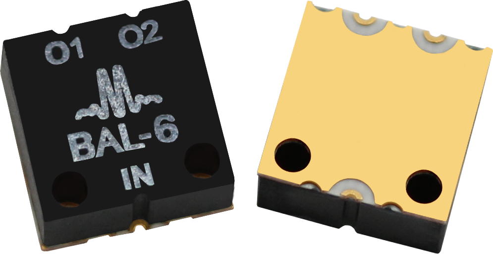
The BAL-0006SMG is a broadband surface mount balun, hand-tuned for optimal phase and amplitude balance over a 500 kHz to 6 GHz bandwidth. It serves as an excellent choice for analog to digital converters, balanced receivers, baseband digital modulations, and signal integrity enhancement.

| Part Number | Description | Package | Packing Size | Green Status | Product Lifecycle | Export Classification |
|---|---|---|---|---|---|---|
| BAL-0006SMG | SURFACE-MOUNT BROADBAND BALUN | SMG | - | REACH RoHS | Released | EAR99 |
| EVAL-BAL-0006 | Evaluation Board, High Power 0.0005 - 6 GHz Broadband Balun | EVAL | - | Non-RoHS | Released | EAR99 |
| BAL-0006SMG-TR | Tape and Reel, SURFACE-MOUNT BROADBAND BALUN | SMG | 13" | REACH RoHS | Released | EAR99 |
BAL-0006SMG
SURFACE-MOUNT BROADBAND BALUN
| Revision Code | Revision Date | Comment |
|---|---|---|
| - | 2013-02-01 | Datasheet initial Release |
| A | 2019-03-01 | Evaluation board outline added |
| B | 2019-10-01 | Mixed Mode Scattering Parameters added |
| C | 2020-04-01 | Unit Spread Graphs Added |
| D | 2020-07-01 | Update Specs table & low frequency Ssd21 plot added |
| E | 2020-10-01 | Update Specs table |
| F | 2022-05-01 | Max DC current update, Ground Plane Finish Update |
| G | 2022-11-01 | Banded Electrical Specifications Added |
| H | 2023-12-21 | Updated Specs table to add sub-banding on certain specifications. |
BAL-0006SMG
SURFACE-MOUNT BROADBAND BALUN
| Port | Function | Description | DC Equivalent Circuit |
|---|---|---|---|
| Common Port / In (Unbalanced) | RF Input | The common port is DC short to ground. |  |
| Out 1 / 0° Port (Balanced) | 0° Port | The 0° port is DC short to ground. | |
| Out 2 / 180° Port (Balanced) | 180° Port | The 180° port is DC short to ground. | |
BAL-0006SMG
SURFACE-MOUNT BROADBAND BALUN
| Parameter | Maximum Rating | Unit |
|---|---|---|
| Maximum Operating Temperature | 100 | °C |
| Maximum Storage Temperature | 125 | °C |
| Minimum Operating Temperature | -55 | °C |
| Minimum Storage Temperature | -65 | °C |
| RF Power Handling | 1 | W |
| Parameter | Details | Rating |
|---|---|---|
| Weight | Package name: SMG | 0.24g |
| Dimensions | - | 8.13 x 8.13 mm |
| Moisture Sensitivity Level | - | MSL 1 |
BAL-0006SMG
SURFACE-MOUNT BROADBAND BALUN
The electrical specifications apply at TA=+25°C in a 50Ω system. Min and Max limits are guaranteed at TA=+25°C.
| Parameter | Test Conditions | Minimum Frequency (GHz) | Maximum Frequency (GHz) | Min | Typ | Max | Unit |
|---|---|---|---|---|---|---|---|
| VSWR | - | 0.0005 | 6 | - | 1.5 | - | - |
| Isolation | - | 0.0005 | 6 | - | 8 | - | dB |
| Impedance Ratio | - | - | - | - | 2:1 | - | - |
| Risetime/Falltime 1 | - | 0.0005 | 6 | - | 17 | - | ps |
| Nominal Phase Shift | - | 0.0005 | 6 | - | 180 | - | ° |
| Amplitude Balance | - | 0.0005 | 0.002 | - | 0.1 | - | dB |
| Amplitude Balance | - | 0.002 | 0.006 | - | 0.1 | 3 | dB |
| Amplitude Balance | - | 0.006 | 6 | - | 0.4 | 1.2 | dB |
| Phase Balance | - | 0.0005 | 0.002 | - | 0.9 | - | ° |
| Phase Balance | - | 0.002 | 0.006 | - | 0.4 | 12 | ° |
| Phase Balance | - | 0.006 | 6 | - | 3 | 10 | ° |
| Common Mode Rejection | - | 0.0005 | 0.002 | - | 39 | - | dB |
| Common Mode Rejection | - | 0.002 | 0.006 | 16 | 45 | - | dB |
| Common Mode Rejection | - | 0.006 | 6 | 20 | 30 | - | dB |
| Insertion Loss as a Mode Converter | - | 0.0005 | 0.002 | - | 3.9 | - | dB |
| Insertion Loss as a Mode Converter | - | 0.002 | 0.006 | - | 3.8 | 6.5 | dB |
| Insertion Loss as a Mode Converter | - | 0.006 | 6 | - | 4 | 5.5 | dB |
[1] Specified as 90%/10%. Calculated from Tau_balun2 = (Tau_out2 – Tau_in2)
BAL-0006SMG
SURFACE-MOUNT BROADBAND BALUN
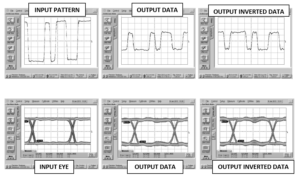
Oscilloscope measurements of the BAL-0006SMG with a 6 Gb/s PRBS pattern. Bit pattern is measured with a 27-1 PRBS input demonstrating extremely good pulse fidelity for both inverted and non-inverted output. Eye diagrams are taken with a 231-1 PRBS input demonstrating minimal eye distortion/closure afforded by the extremely low frequency operation of the balun (<500 kHz).
BAL-0006SMG
SURFACE-MOUNT BROADBAND BALUN
Mixed mode scattering parameters are used to characterize differential circuits. For baluns, this means that the 0° and 180° ports become a single 100Ω differential port and the common port remains the same 50Ω common port. The two-port s-parameters of the balun are then characterized based on differential (d), common mode (c), or single-ended (s) signals. For example: Sds12 is the differential output response given a single ended input.


BAL-0006SMG
SURFACE-MOUNT BROADBAND BALUN


BAL-0006SMG
SURFACE-MOUNT BROADBAND BALUN
BAL-0006SMG
SURFACE-MOUNT BROADBAND BALUN
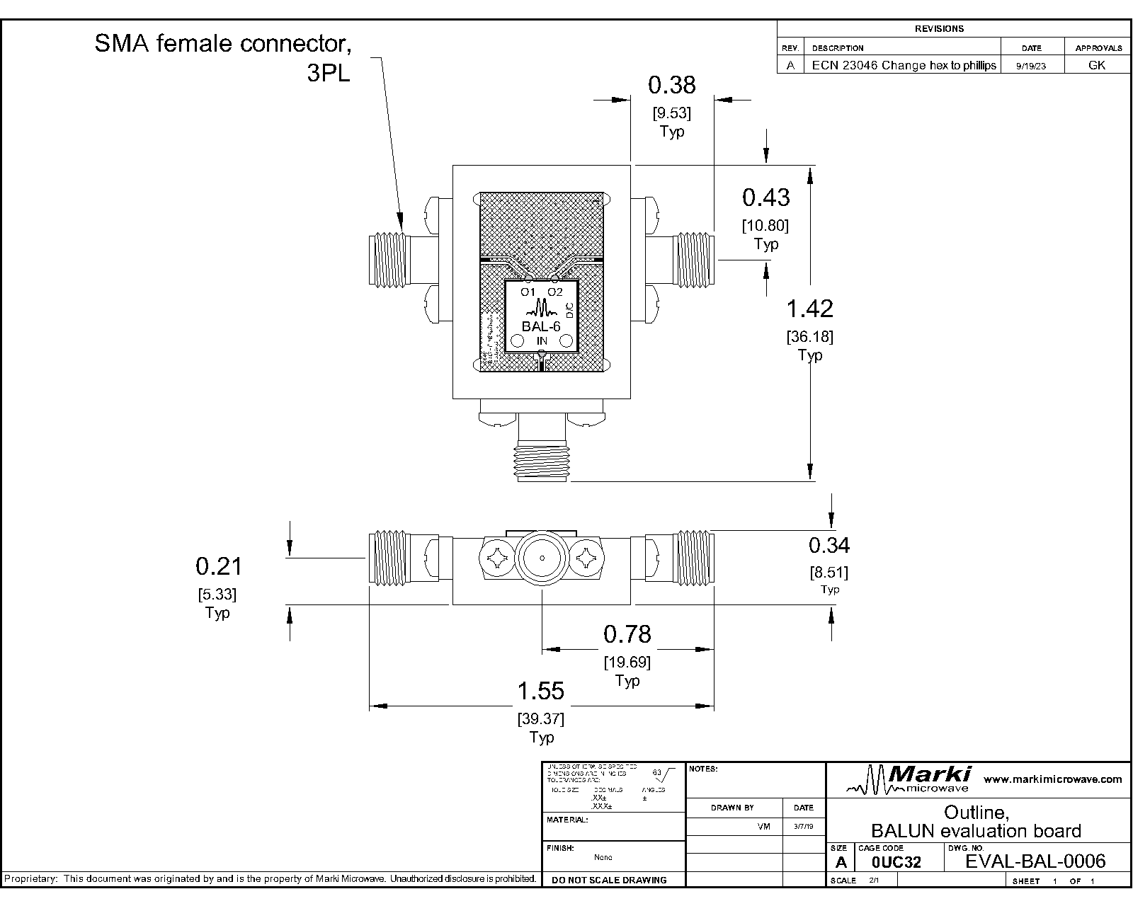
Download : Outline 2D Drawing Outline 3D Drawing Outline 3D STP

Substrate material is 8-mil thick Rogers 4003, 1 Oz Electrodeposited Cu. I/O Pads & Ground Plane Finish is Gold Flash, 5 to 10 µinches, over Electroplated Nickel, 100-200 µ-inches, over Cu.
BAL-0006SMG
SURFACE-MOUNT BROADBAND BALUN
Download : Footprint Drawing

BAL-0006SMG
SURFACE-MOUNT BROADBAND BALUN
| Parameter | Test Conditions | Frequency Range (GHz) | Min | Typ | Max | Unit |
|---|---|---|---|---|---|---|
| Impedance Ratio | - | - | - | 2 | - | - |
BAL-0006SMG
SURFACE-MOUNT BROADBAND BALUN