Rev: - | Copyright © 2026 Marki Microwave LLC.

General Description

The ABSD-11278PSM is a GaAs active MMIC balun in a 3mm QFN surface mount package. Its frequency ranges from DC to 12 GHz. The ABSD-11278PSM operates from a single supply voltage, enabling low power consumption. The 3mm QFN package is a lead free, RoHS compliant package compatible with standard leaded and lead-free solder reflows. Connectorized evaluation packages are available. The ABSD-11278PSM is an excellent choice for single ended to differential mode conversion and higher order Nyquist sampling in analog to digital converters.

Features

  • 2:1 Impedance Ratio
  • 12 GHz Active Balun (Single Ended to Differential Mode Conversion)
  • Designed for low power consumption
  • High linearity HD2 and HD3
  • Single Supply Voltage, +5V/49mA

Functional Block Diagram

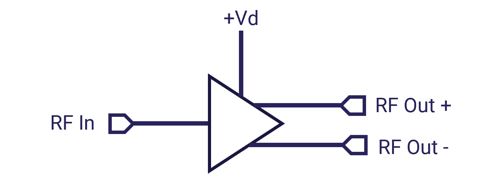
Block Diagram
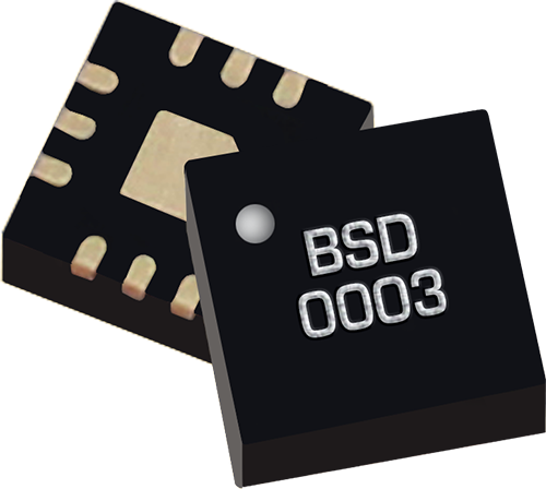
Photo of ABSD-11278PSM

Electrical Performance Summary

ParameterTypUnit
Frequency Range0 to 12GHz
Insertion Loss 6.3dB
Phase Balance 0.5°
Amplitude Balance 0.25dB
Impedance Ratio 2:1-

Summary only – refer to the Electrical Specifications, Absolute Maximum Ratings, and Recommended Operating Range tables for complete details.

Part Ordering Options

Part NumberDescriptionPackageGreen StatusProduct LifecycleExport Classification
ABSD-11278PSM12 GHz Single Ended to Differential Active BalunQFN

REACH

RoHS

ReleasedEAR99
EVB-ABSD-11278PEvaluation BoardEVBReleased-

Table Of Contents

Typical Performance Plots

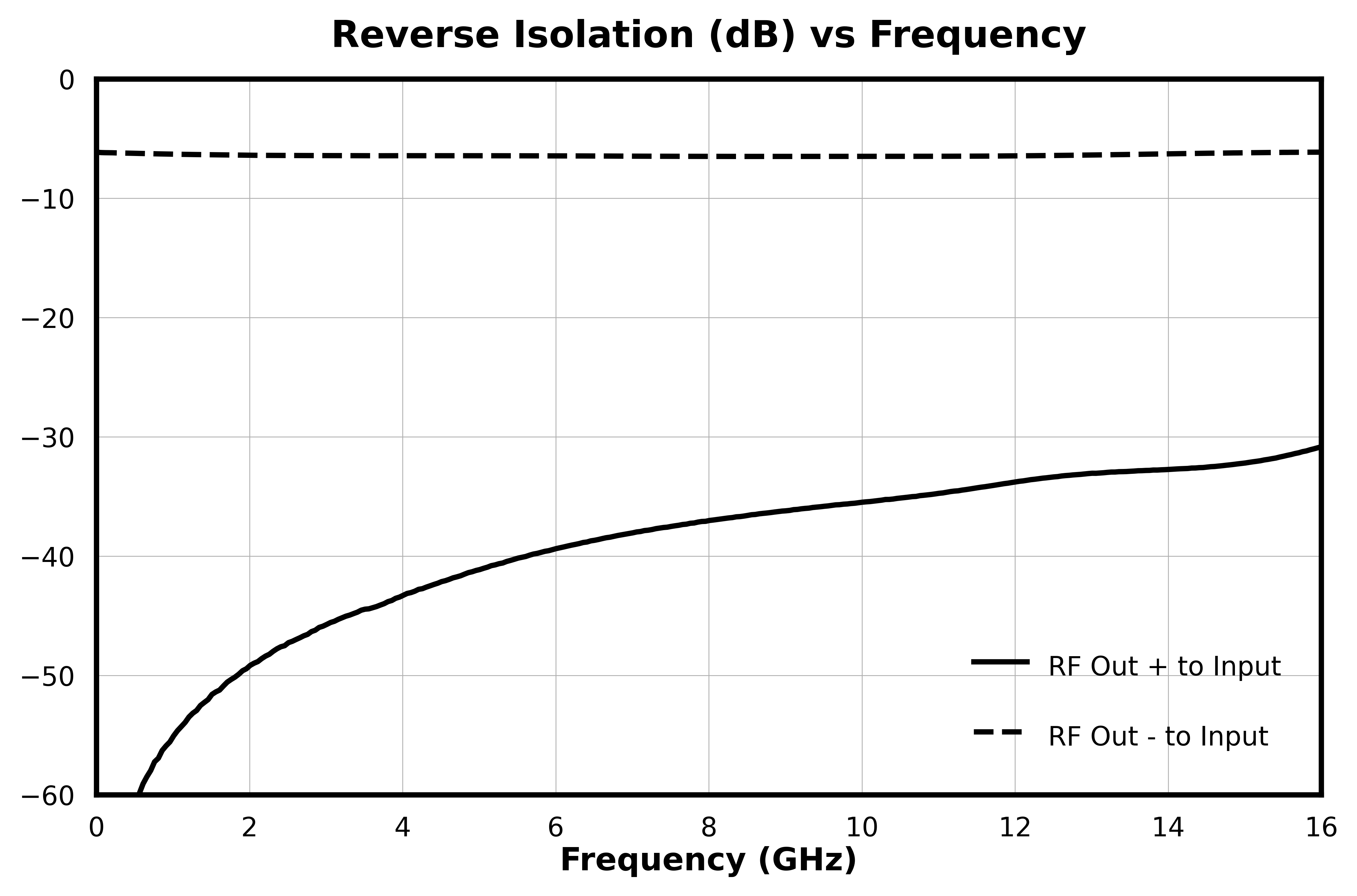
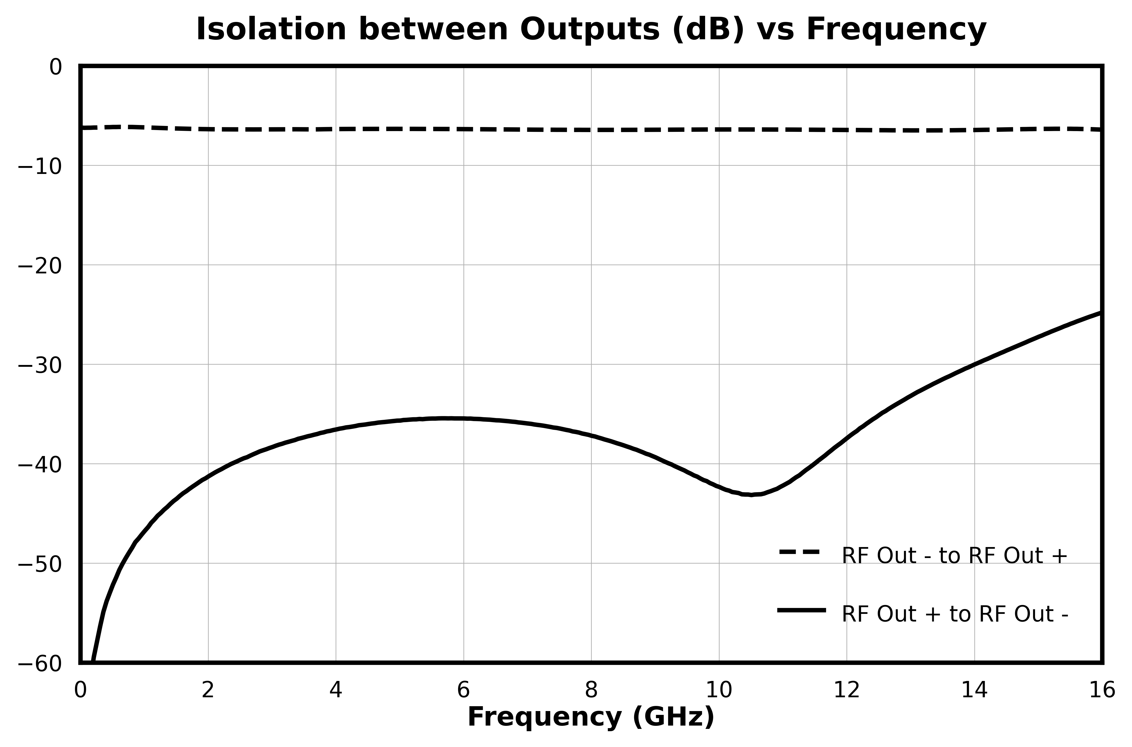
Three-port scattering parameters measured as three single-ended 50Ω ports unless otherwise noted. Small signal gain, return losses and reverse isolation have evb and connector effects de-embedded.

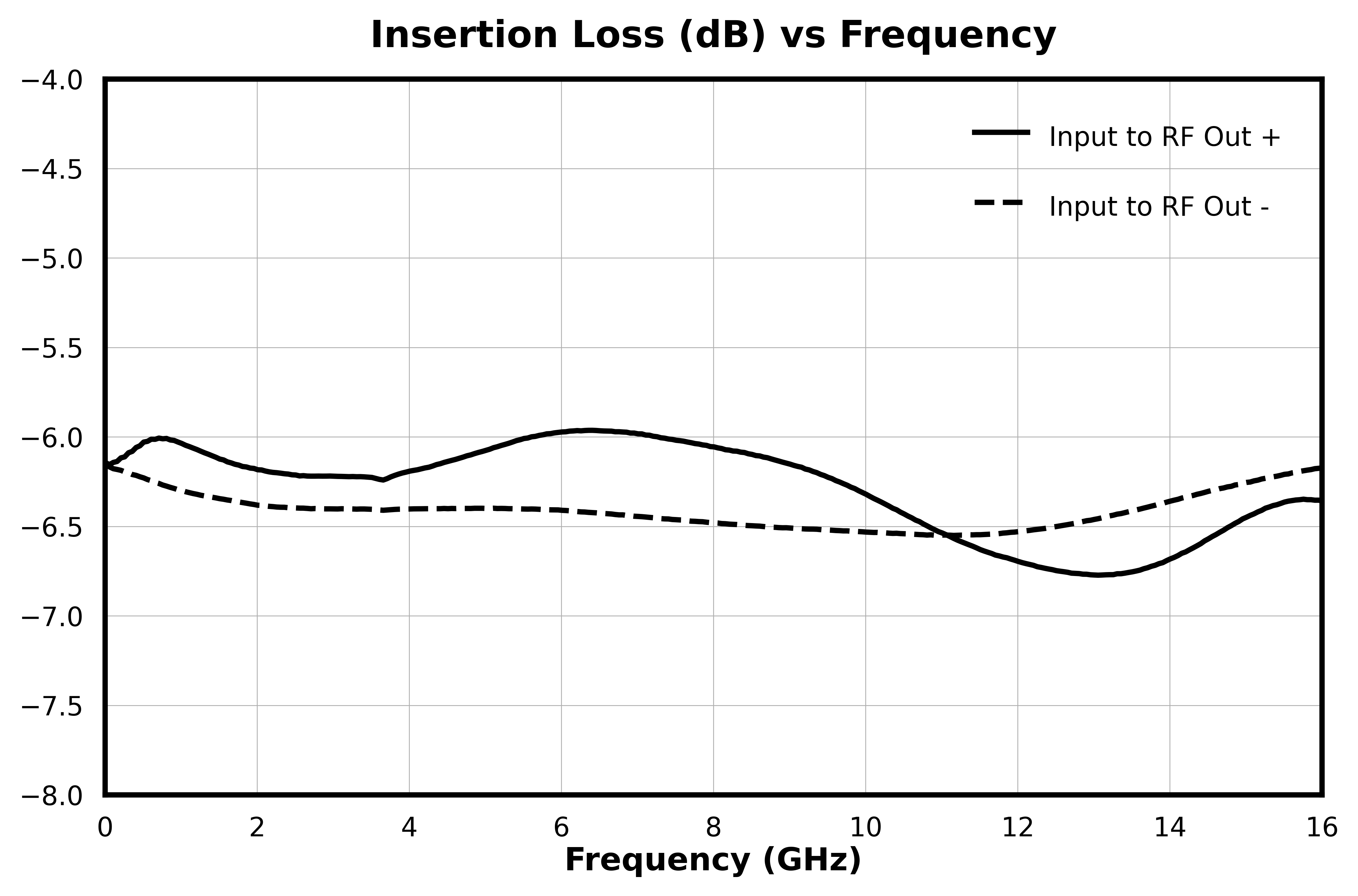
Common to output port insertion loss graph for ABSD-11278PSM
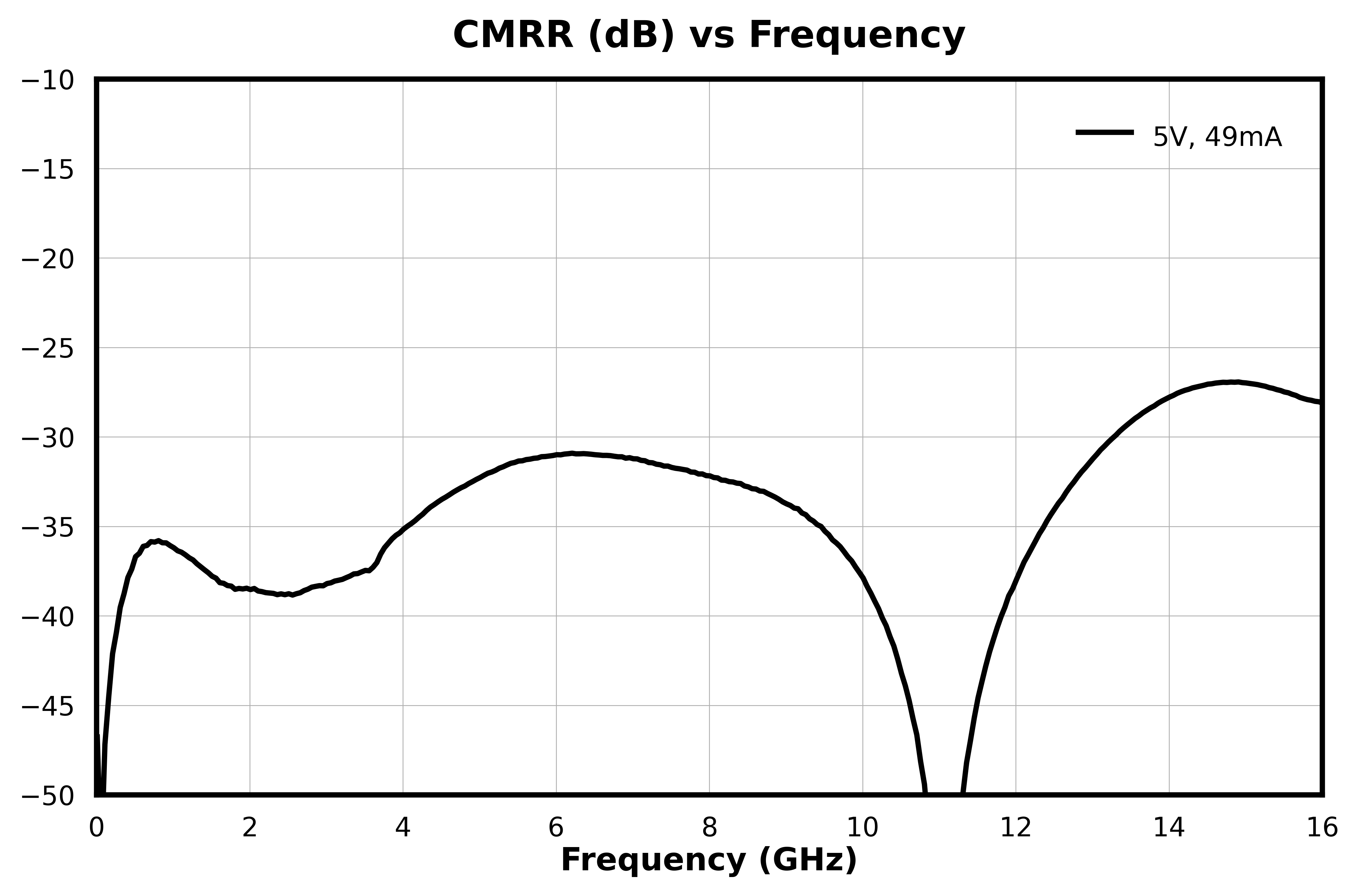
Common mode rejection graph for ABSD-11278PSM
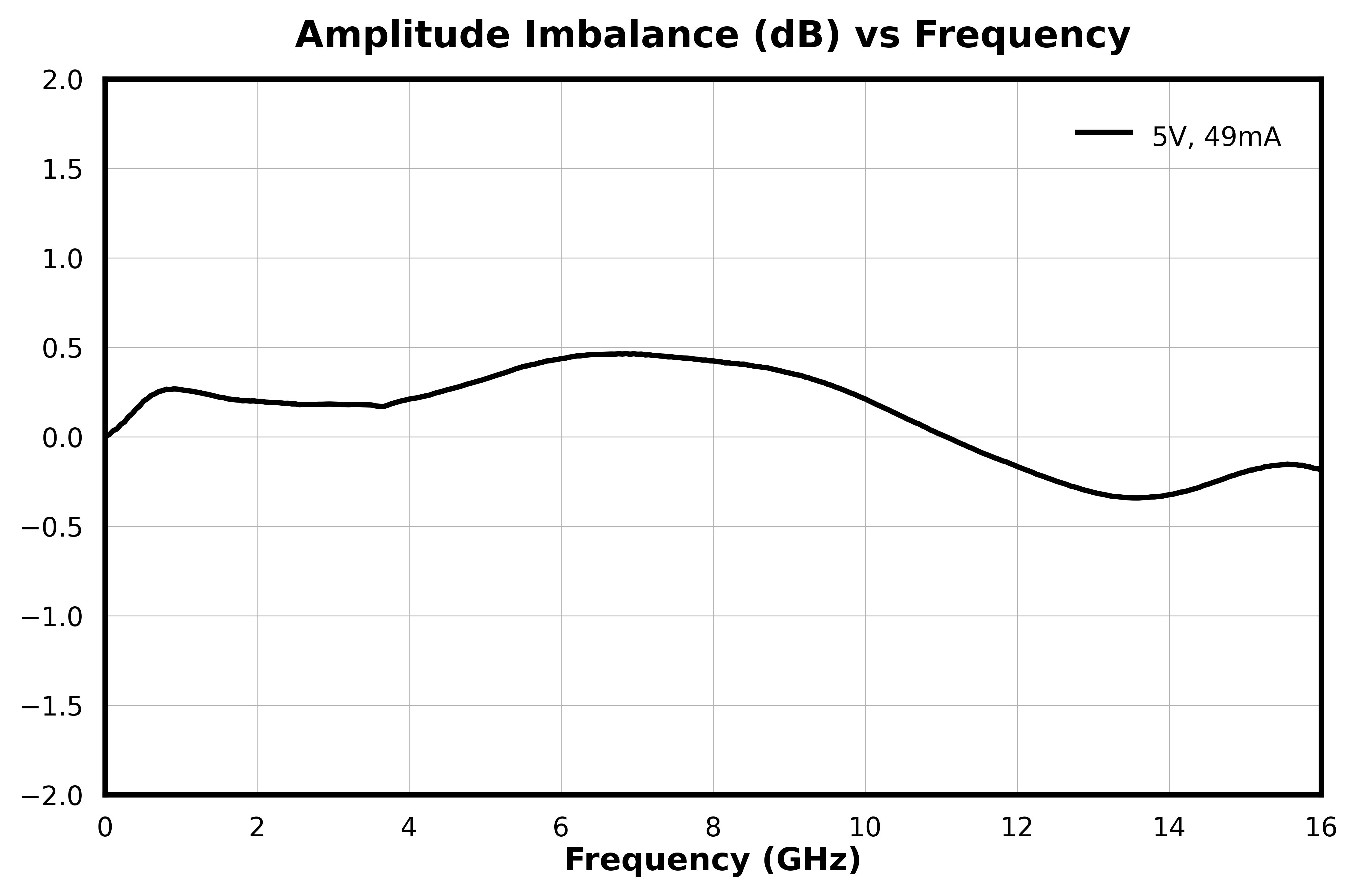
Amplitude balance between output ports graph for ABSD-11278PSM
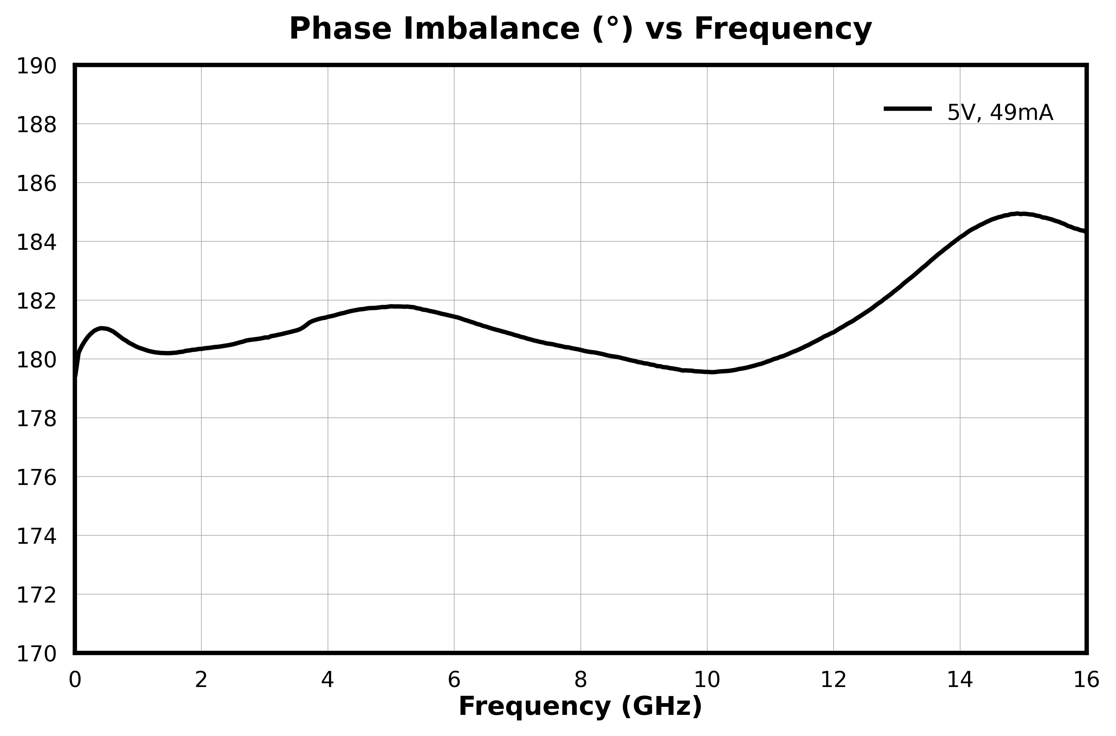
Phase balance between output ports graph for ABSD-11278PSM
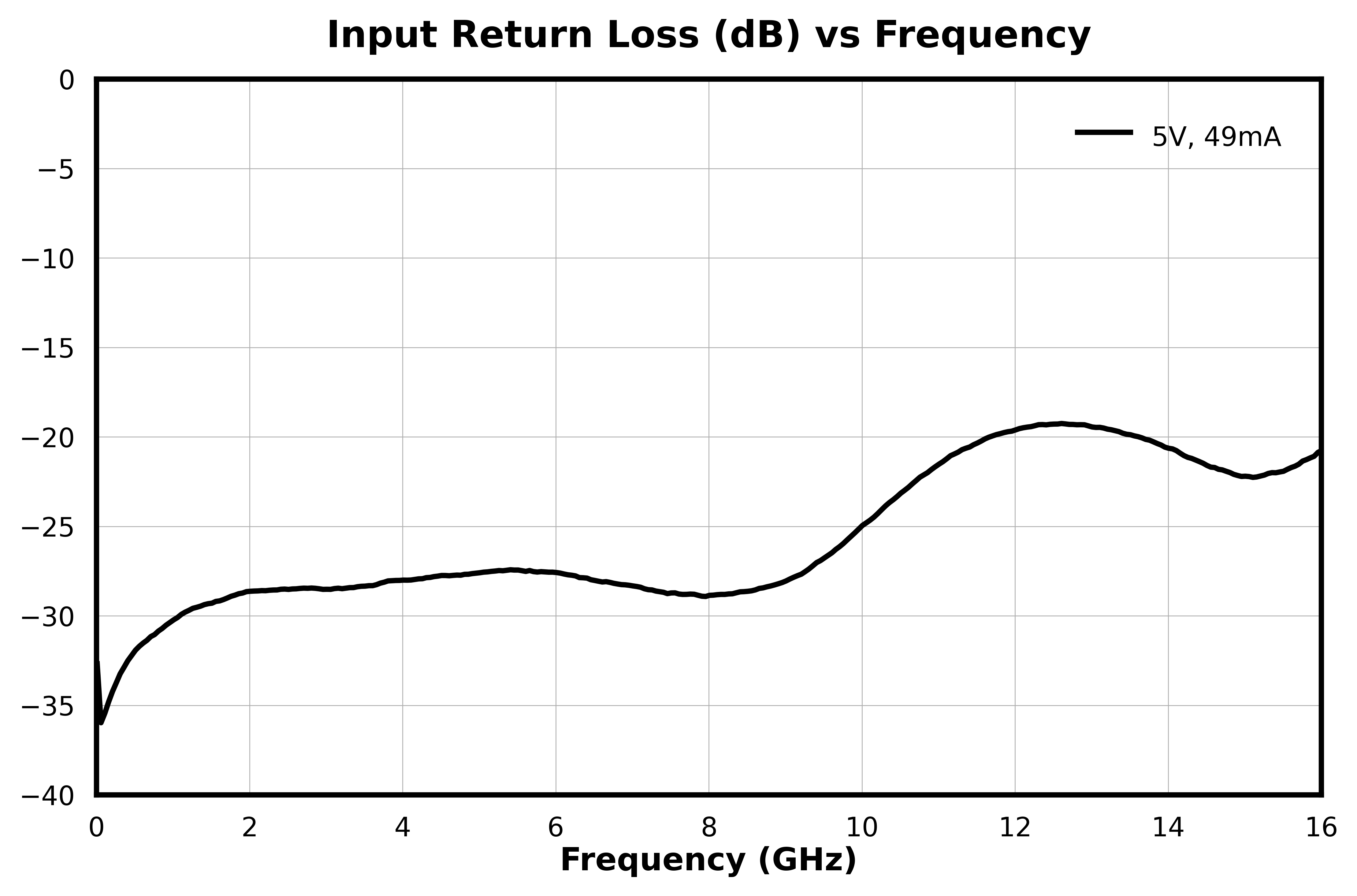
Input Return Loss graph for ABSD-11278PSM
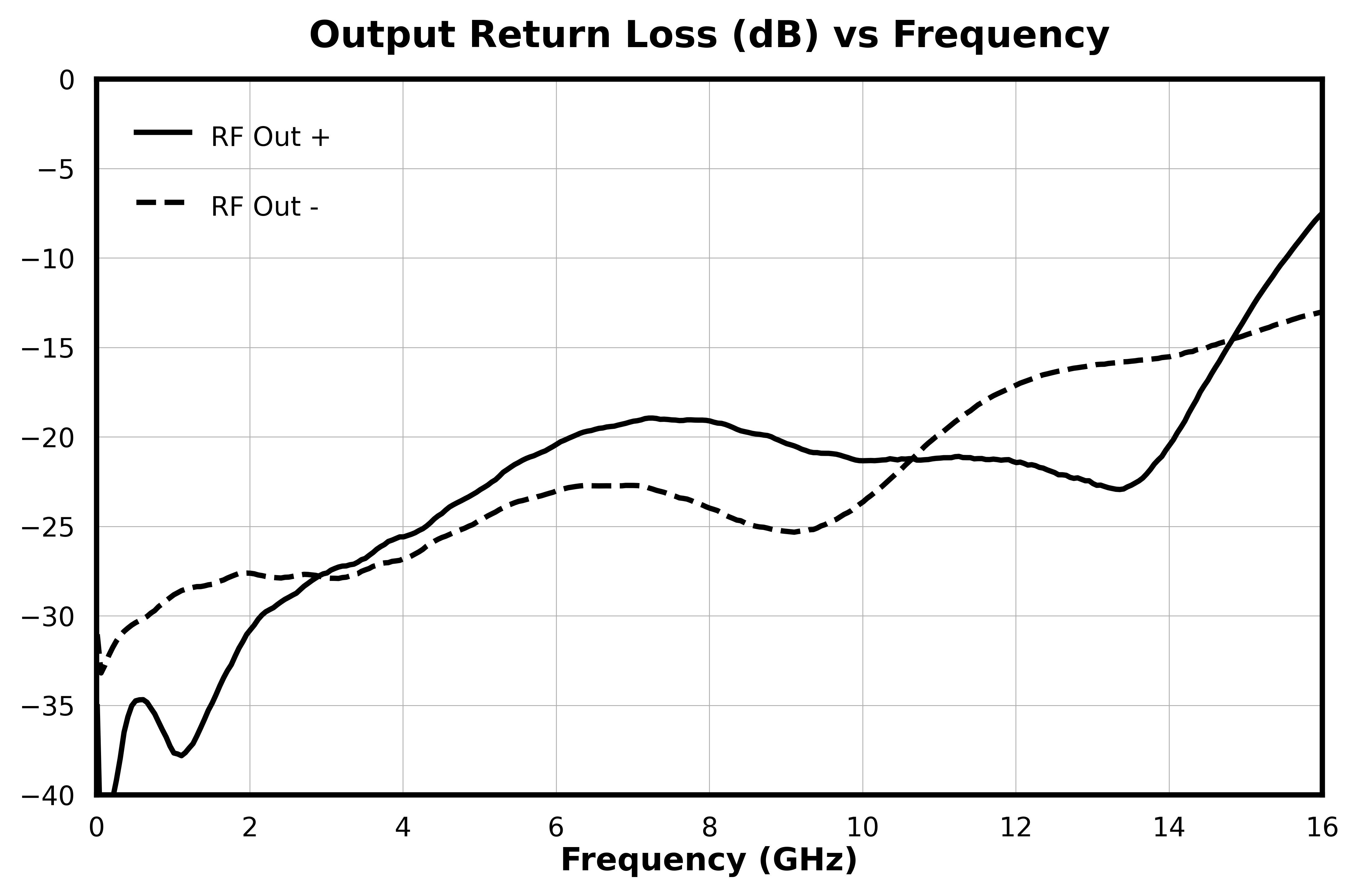
Output Return Loss graph for ABSD-11278PSM
Reverse Isolation graph for ABSD-11278PSM
Isolation between output ports graph for ABSD-11278PSM

Differential Linearity

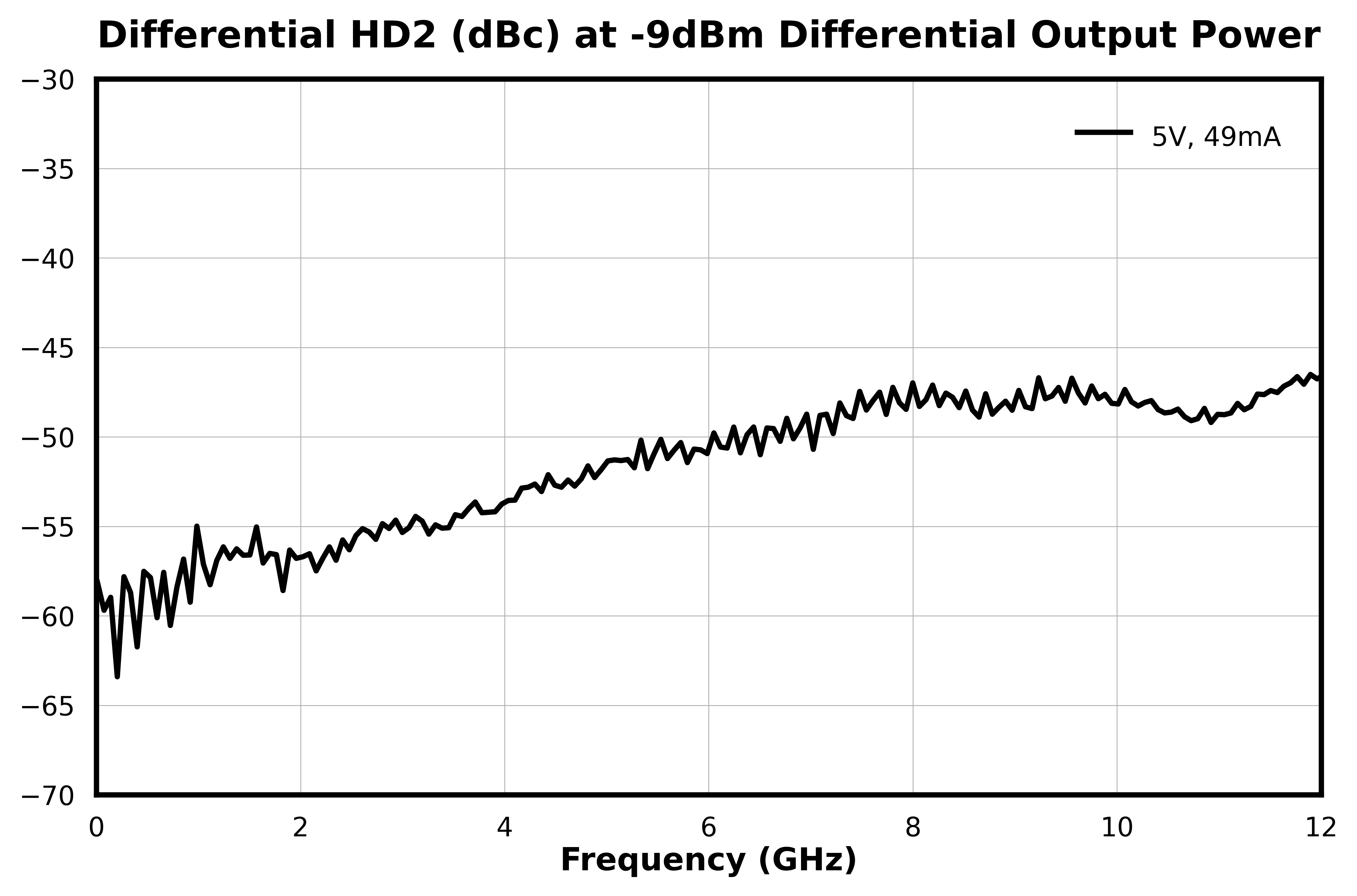
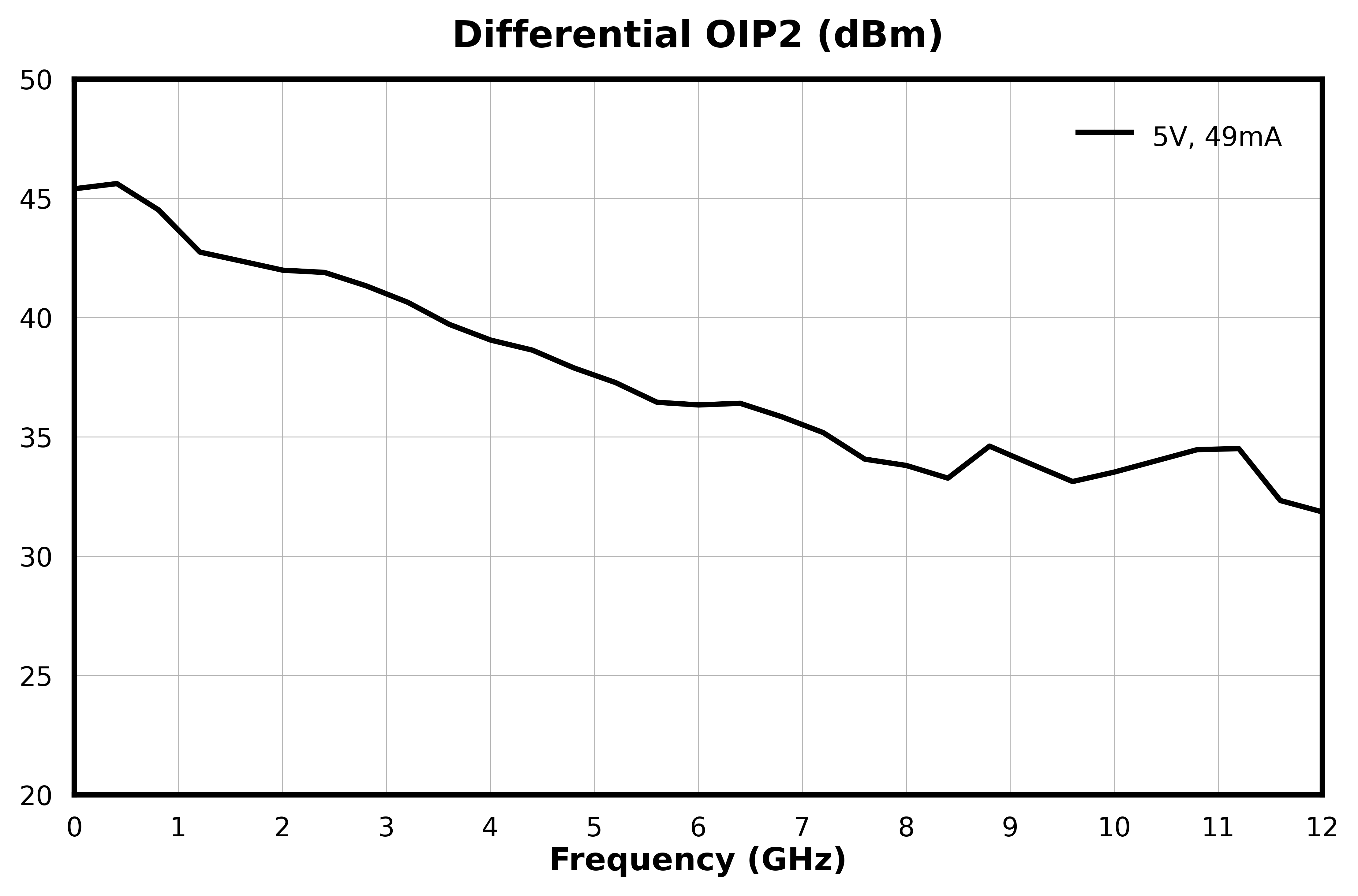
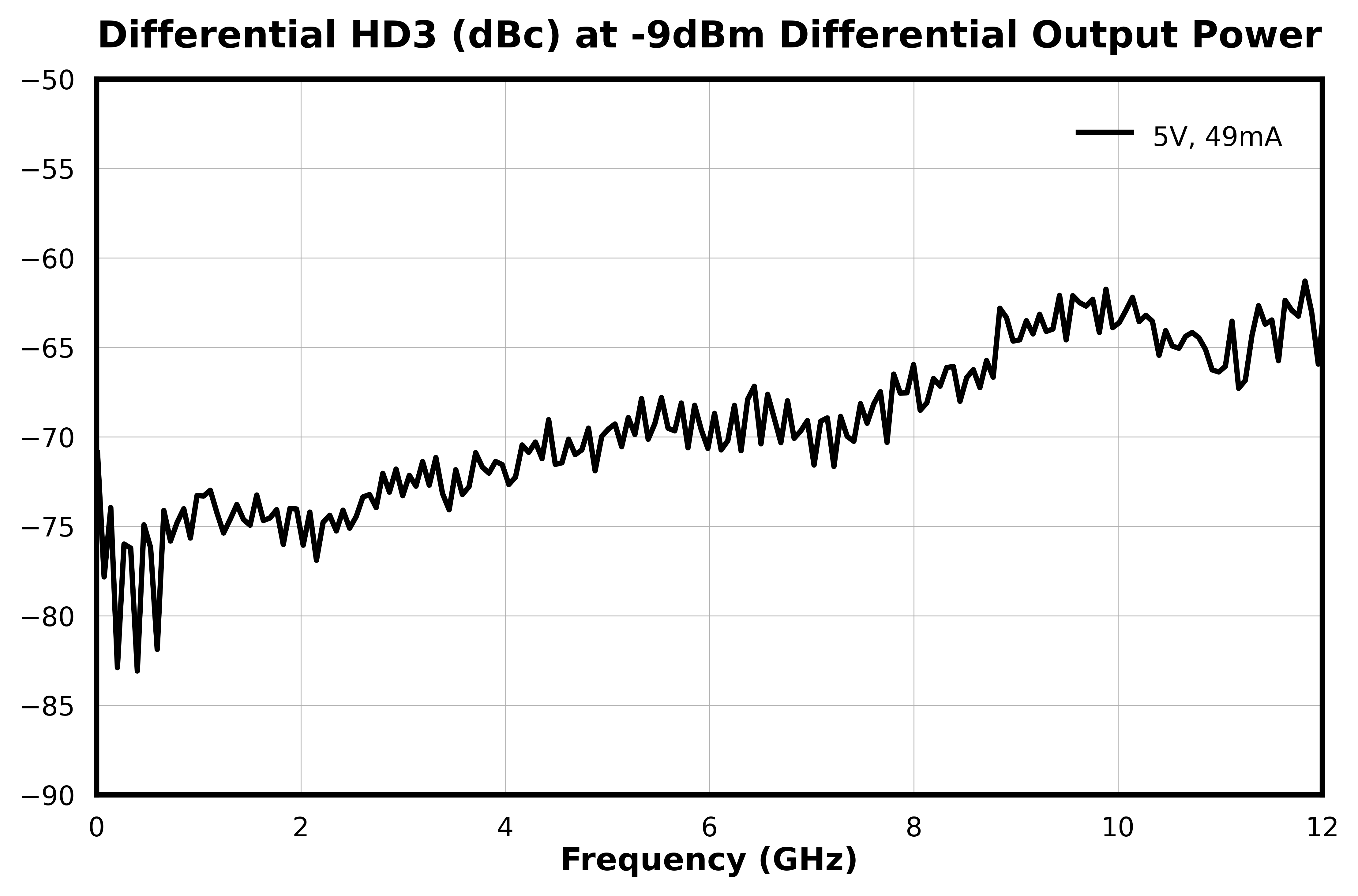
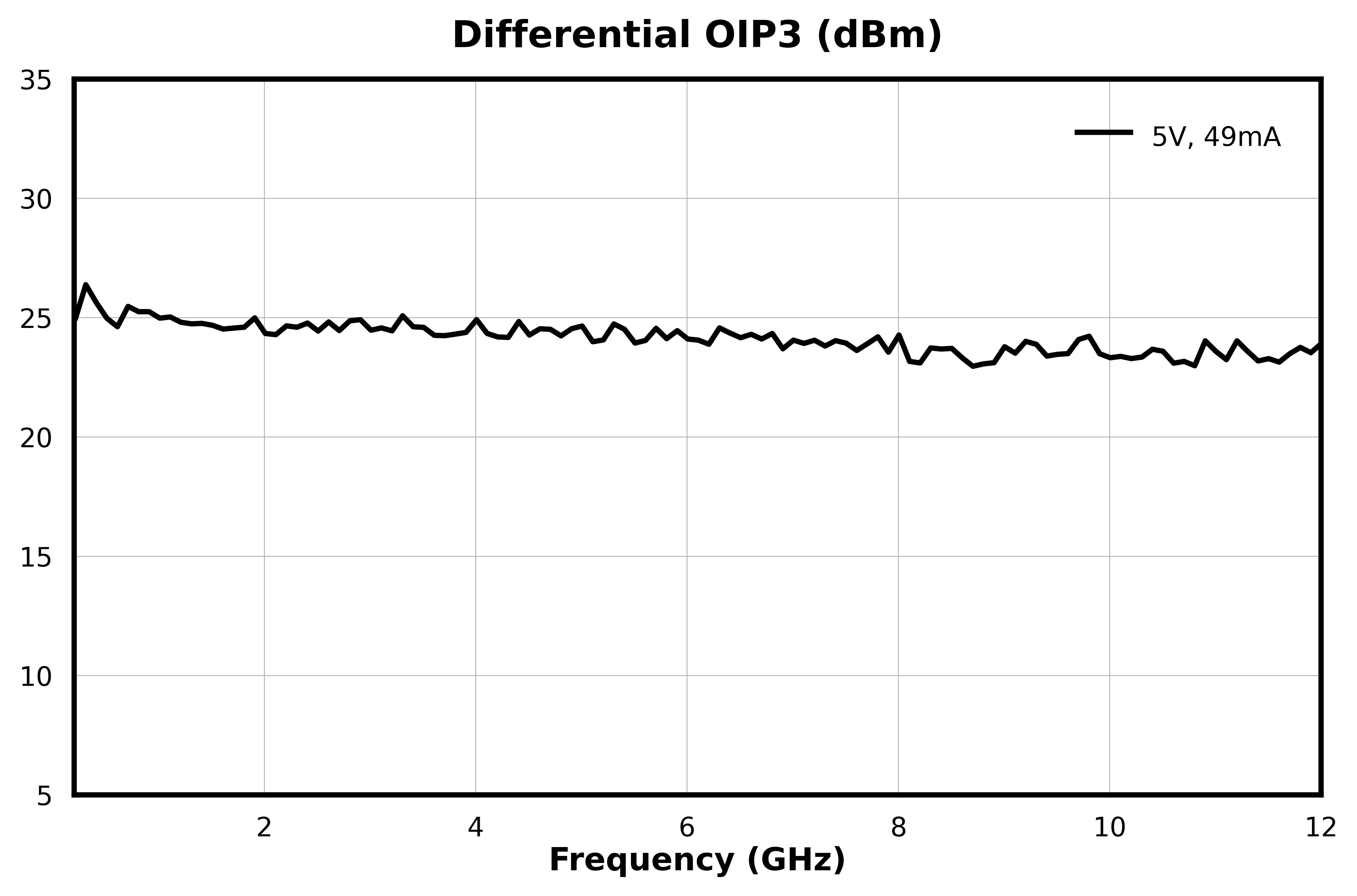
Measurements are with 50-Ω single-ended input, and 100-Ω differential output. EVB and connector effects are included in these measurements.

HD2 (dBc) graph for ABSD-11278PSM
OIP2(dBm) vs. Frequency graph for ABSD-11278PSM
HD3 (dBc) graph for ABSD-11278PSM
OIP3 (dBm) graph for ABSD-11278PSM

Noise Figure

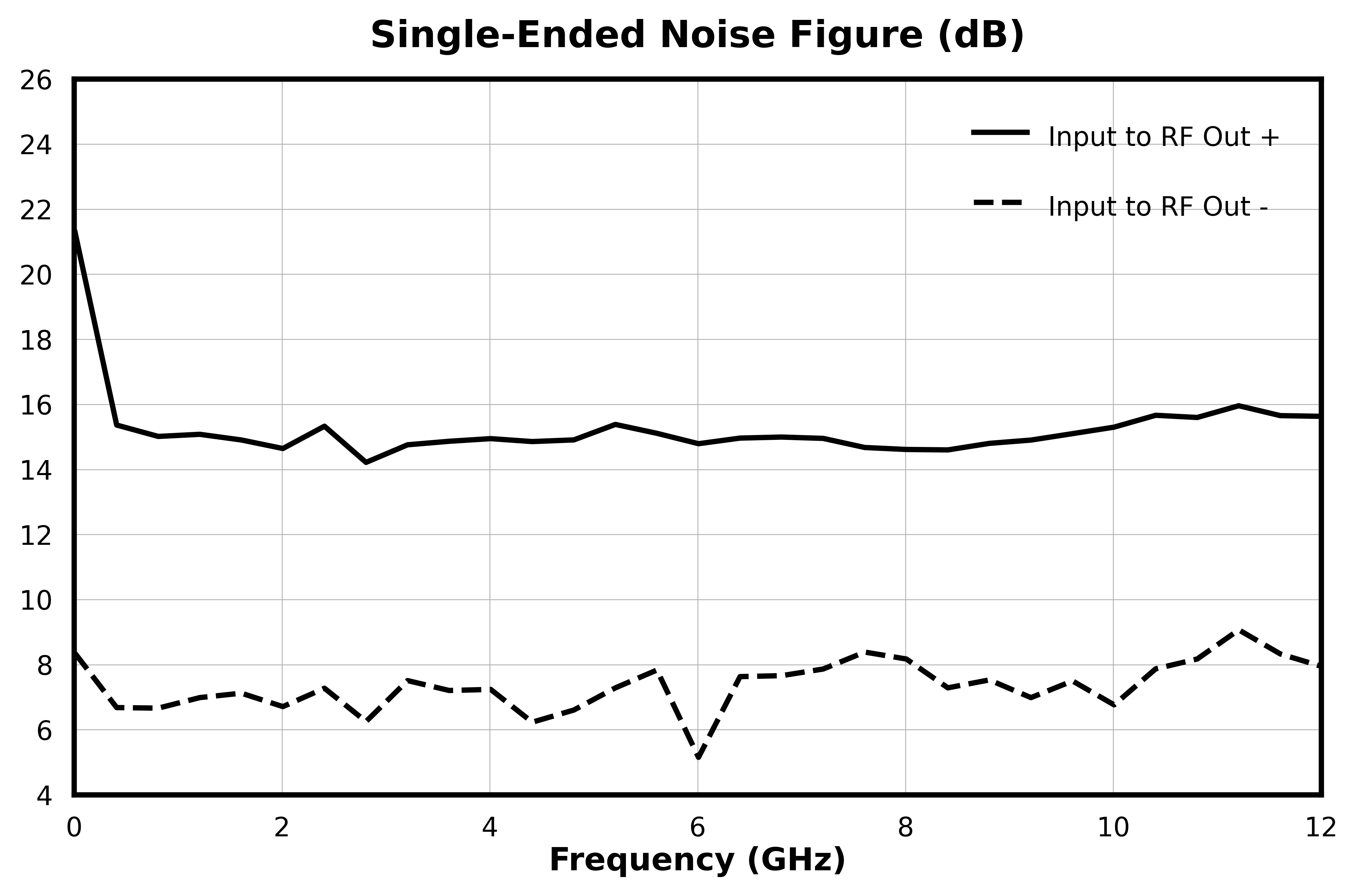
Measured as two single-ended Noise Figure measurements with unused port terminated in 50 ohm load.

Noise Figure (dB) vs. Frequency graph for ABSD-11278PSM

Specifications

Electrical Specifications

Specifications guaranteed for +25°C, measured in a 50Ω system. Measured data was taken on an evaluation board and includes PCB trace and connector effects unless otherwise noted.

ParameterTest ConditionsMinimum
Frequency
(GHz)
Maximum
Frequency
(GHz)
MinTypMaxUnit
Frequency Range-0 12---GHz
OIP2 Differential OIP2, measured at -5dBm input power
0 12-36-dBm
OIP3 Differential OIP3, measured at -5dBm input power
0 12-24-dBm
Noise Figure Single-Ended Noise Figure, Input to RF Out +
0 12-15-dB
Noise Figure Single-Ended Noise Figure, Input to RF Out -
0 12-7.3-dB
Reverse Isolation RF Out + to Input
0 12--40-dB
Reverse Isolation RF Out - to Input
0 12-6-dB
Isolation between differential ports Insertion Loss going from RF Out + to RF Out -
0 12-39-dB
Isolation between differential ports Insertion Loss going from RF Out - to RF Out +
0 12-6-dB
Amplitude Balance 5V/49mA
0 12-0.25-dB
Common Mode Rejection Ratio 5V/49mA
0 12-36-dB
Common Port Return Loss 15V/49mA
0 12-28-dB
DC Supply Quiescent Current (Idq) Vd=5V
- --49-mA
HD2 Differential HD2 (dBc) at 5V/49mA, differential output power=-9dBm
0 12--51-dBc
HD3 Differential HD3 (dBc) at 5V/49mA, with differential output power=-9dBm
0 12--70-dBc
Impedance Ratio -- --2:1--
Insertion Loss 25V/49mA
0 12-6.3-dB
Nominal Phase Shift 5V/49mA
0 12-180-°
Output Return Loss 35V/49mA
0 12-22-dB
Phase Balance 5V/49mA
0 12-0.5-°

[1][2][3] Measured single-ended with connector and evb effects de-embedded.

ParameterMinNominalMaxUnit
Positive DC Voltage (Vd) 555V
Positive DC Current (Id) (No RF Input) 494949mA

Absolute Maximum Ratings

The Absolute Maximum Ratings indicate limits beyond which damage may occur to the device. If these limits are exceeded, the device may be inoperable or have a reduced lifetime. This device is designed and characterized in a 50Ω system (100Ω differential output), and operation in a reflective environment can cause performance degradation.

ParameterMaximum RatingUnit
Drain Current (Id) (No RF Applied) 160mA
Drain Supply Voltage (Vd) 5V
Maximum Operating Temperature 85°C
Maximum Storage Temperature 150°C
Minimum Operating Temperature -40°C
Minimum Storage Temperature -65°C
RF Input Power 15dBm
Thermal Resistance, θJC 62ºC/W

[1] Max current density across TFR

Package Information

ParameterDetailsRating
ESD< 50 VoltsHBM 0Z
Dimensions-3 x 3 mm
Moisture Sensitivity Level-MSL 1

Port Configuration and Functions

Port Diagram

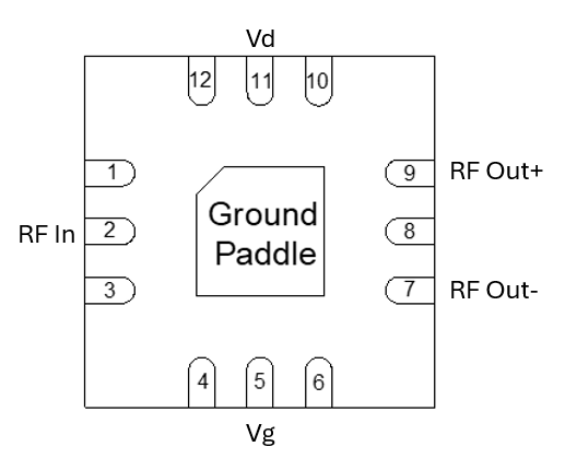
Below is the port diagram for the ABSD-11278PSM. The diagram is shown as an x-ray view from the top down.

Diagram of the port configuration for ABSD-11278PSM

Port Functions

PortFunctionDescriptionDC Equivalent
Circuit
11Vd Pin 11 is the positive DC supply voltage for the device. Connect to +5V for normal operation. -
1,3,4,6,8,10 and 12Non-connect (NC) These pins are not connected internally. Datasheet performance is tested with NC pins grounded.-
2RF Input Pin 2 is the RF input of the device. This pin is internally RF matched to 50 Ohms and is DC coupled. This pin requires an external DC blocking capacitor.-
5Vg Pin 5 is connected to an internal DC voltage for the device. This pin should be left open for normal operation. Do not connect to ground.-
7RF Out - Pin 7 is the negative RF output of the device. This pin is internally RF matched to 50 Ohms and is DC coupled. This pin requires an external DC blocking capacitor.-
9RF Out + Pin 9 is the positive RF output of the device. This pin is internally RF matched to 50 Ohms and is DC coupled. This pin requires an external DC blocking capacitor.-
PaddleGround Ground pad should be connected to RF/DC ground with low electrical and thermal resistance.-

Operation

Application Circuit

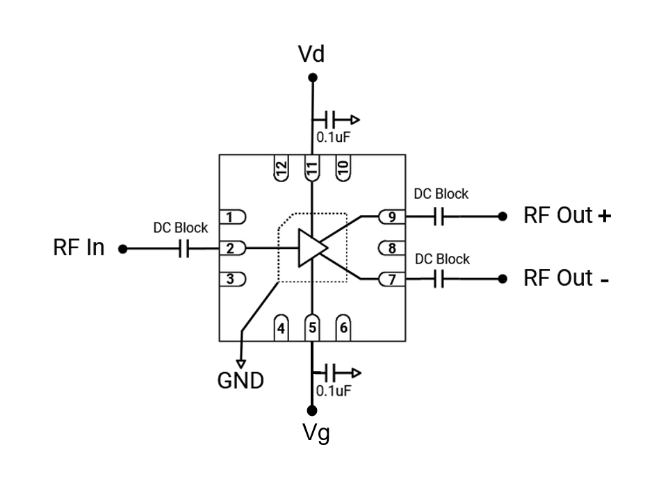
Application Circuit for ABSD-11278PSM

Application Circuit Description

The application circuit for the ABSD-11278PSM is shown above. This part requires DC blocking capacitors at all RF pins ( 2,7 and 9). DC power is supplied via Vd (pin 11). It is recommended to provide 0.1uF bypass capacitors connected to Vd and Vg. Do not apply DC voltage to Vg pin. NC pins are not internally connected but should be grounded. The paddle of the QFN should be connected to GND via a low thermal and electrical resistance.

Mechanical Data

Outline Drawing

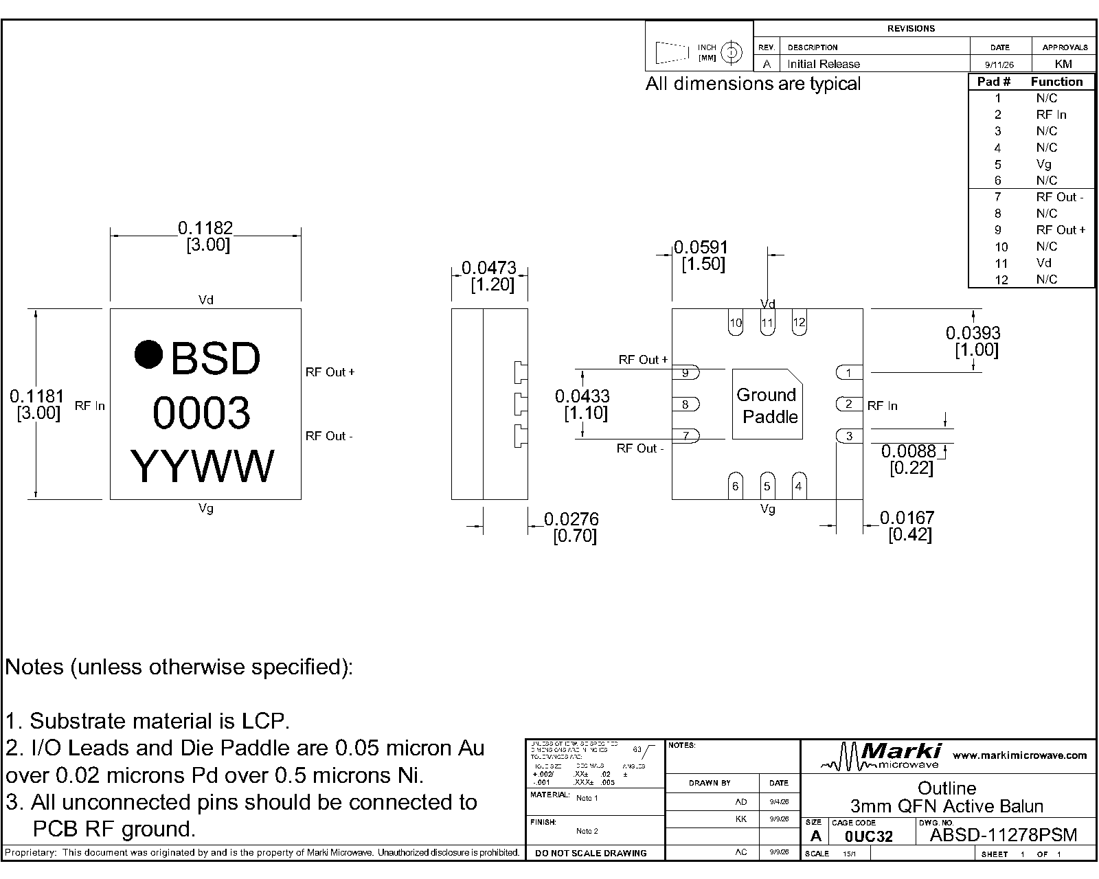
Download : Outline 2D Drawing

Outline Drawing

Evaluation Board

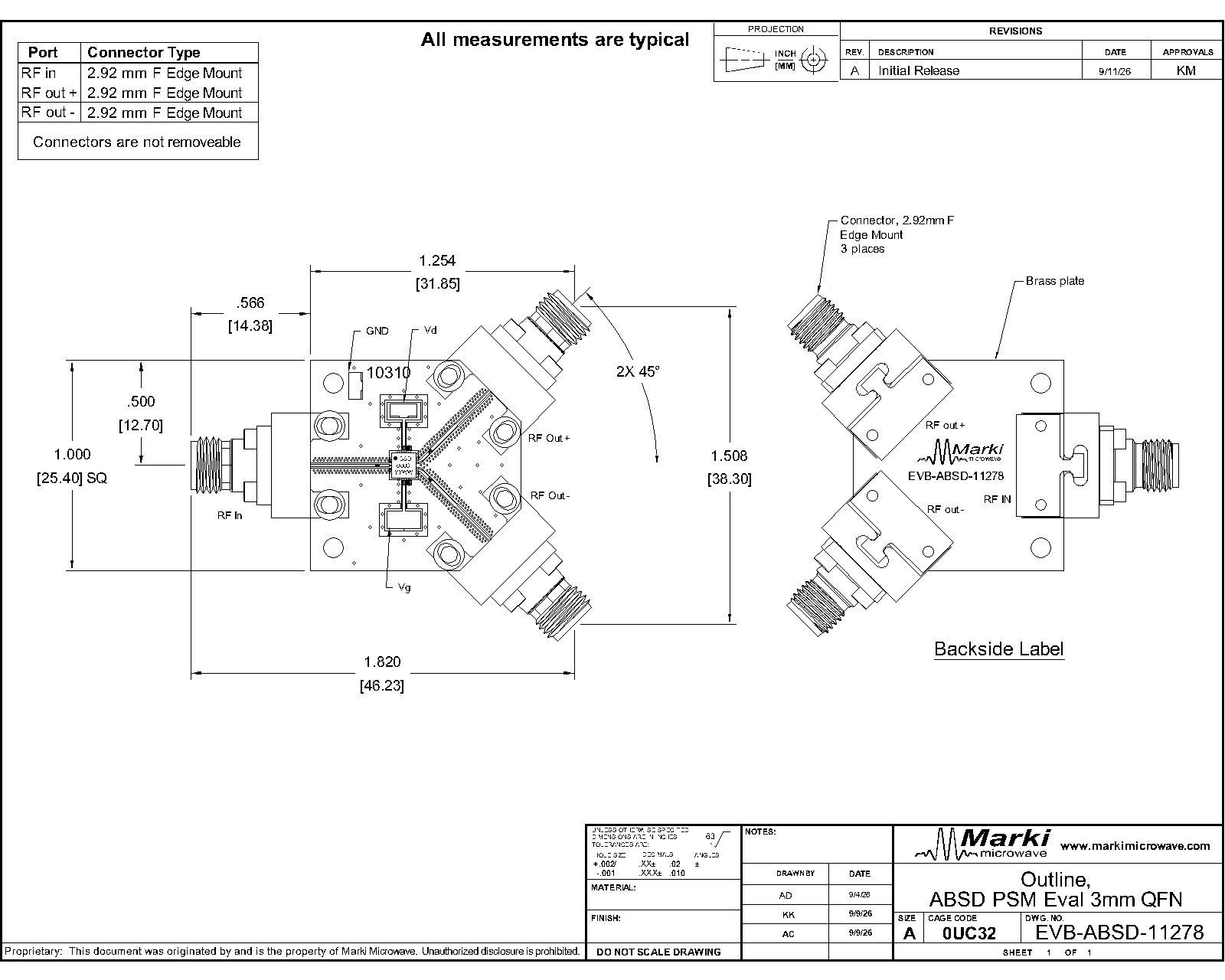
Evaluation Board - Outline Drawing

Outline Drawing

Revision History

Revision CodeRevision DateComment
-2026-11-10Initial Release

Notes

The RF transitions on the input and output traces of the recommended footprint are specific to the material type and thickness used on the Marki evaluation board. They are currently designed for single-ended 50 Ohm transmission line. They will need to be re-designed for pcb stackups using different materials and or different transmission line impedances.

DISCLAIMER

MARKI MICROWAVE, LLC., (“MARKI”) PROVIDES TECHNICAL SPECIFICATIONS AND DATA (INCLUDING DATASHEETS), APPLICATION OR OTHER DESIGN ADVICE, WEB TOOLS, AND OTHER INFORMATION AND RESOURCES “AS IS” AND WITH ALL FAULTS. MARKI DISCLAIMS ALL WARRANTIES, EXPRESS OR IMPLIED, INCLUDING, WITHOUT LIMITATION, ANY IMPLIED WARRANTIES OF MERCHANTABILITY, FITNESS FOR A PARTICULAR PURPOSE, OR NON-INFRINGEMENT.

These resources are intended for developers skilled in the art designing with Marki products. You are solely responsible for (1) selecting the appropriate products for your application, (2) designing, validating, and testing your application, and (3) ensuring your application meets applicable standards and other requirements. Marki makes no guarantee regarding the suitability of its products for any particular purpose, nor does Marki assume any liability whatsoever arising out of your use or application of any Marki product.

Marki grants you permission to use these resources only for development of an application that uses Marki products. Other reproduction or use of these resources is strictly prohibited. No license is granted to any other Marki intellectual property or to any third-party intellectual property. Marki reserves the right to make changes to the product(s) or information contained herein without notice.

MARKI MICROWAVE, M wave logo, FastSwitch, and T3 MIXER are trademarks or registered trademarks of Marki Microwave, LLC. All other trademarks used are the property of their respective owners.

© 2026, Marki Microwave, LLC