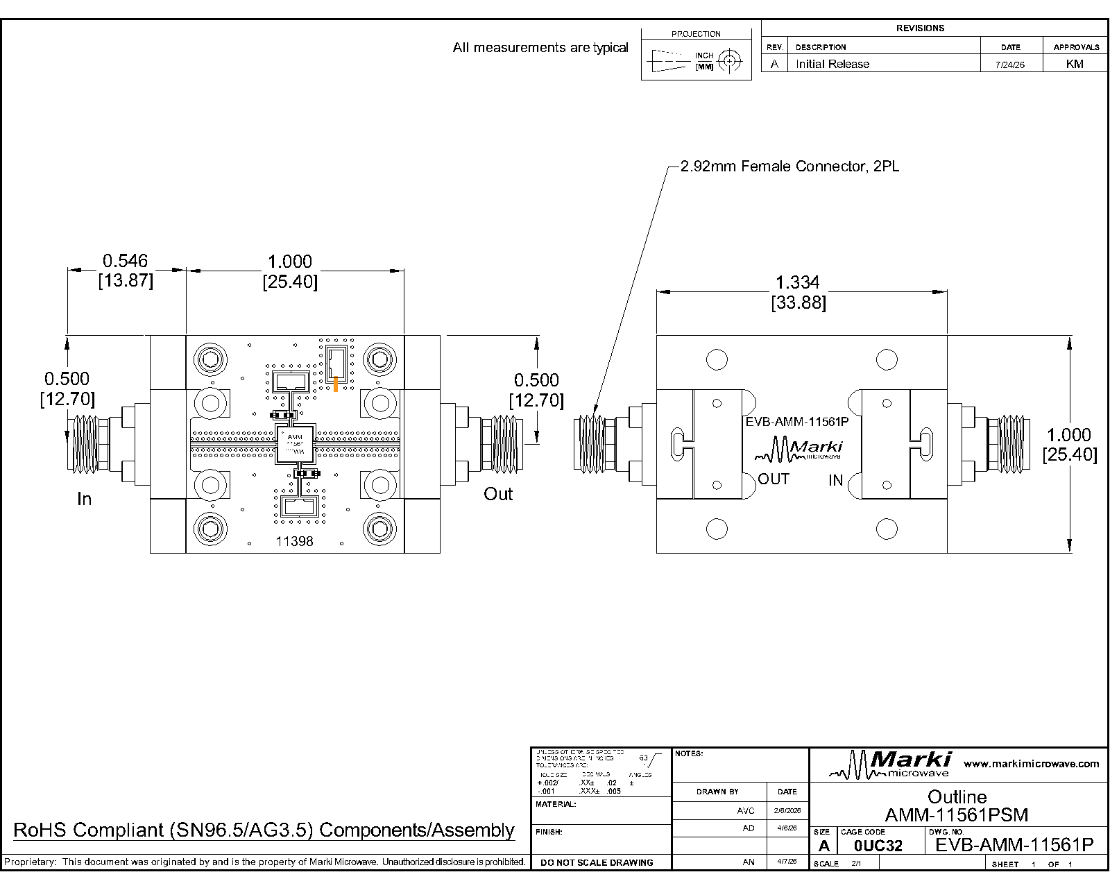
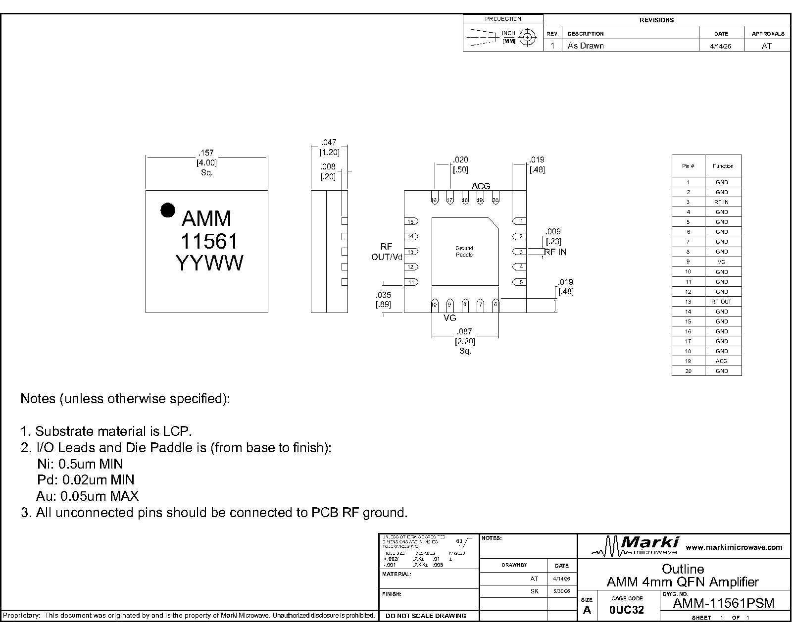
Port Diagram
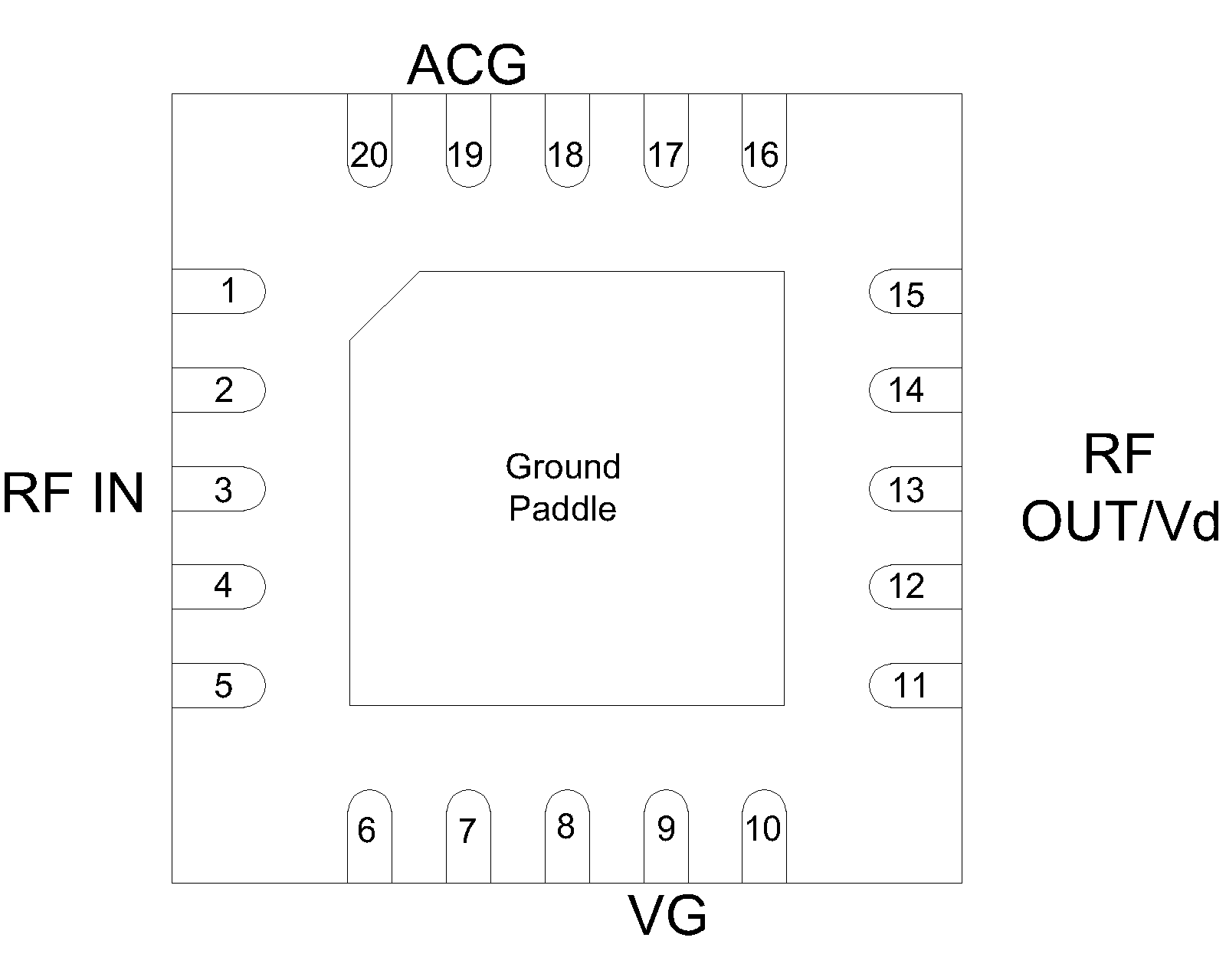
A port diagram of the AMM-11561PSM QFN package is shown below (X-ray view from the top).

Sales: 408-778-9952 | General: 408-778-4200 | Fax: 408-778-4300
Sales & Customer Support: [email protected]
Tech Support: [email protected]
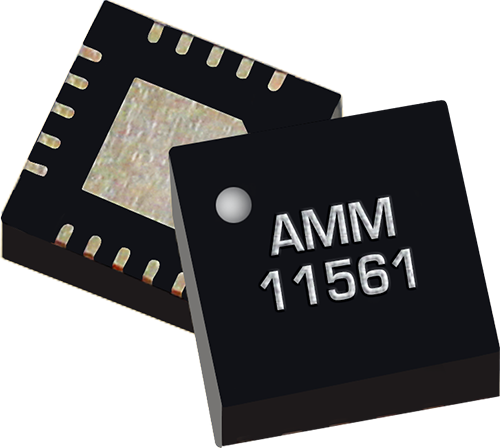
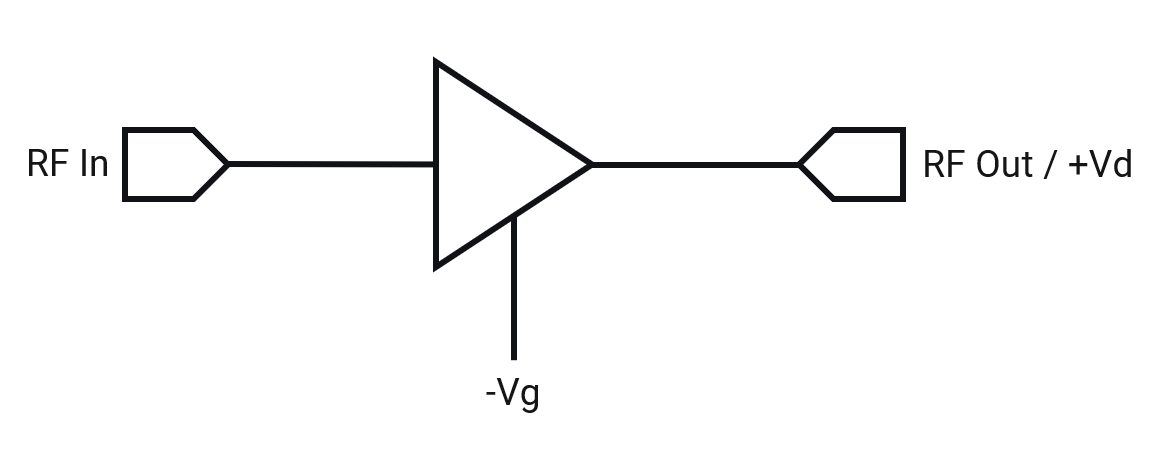
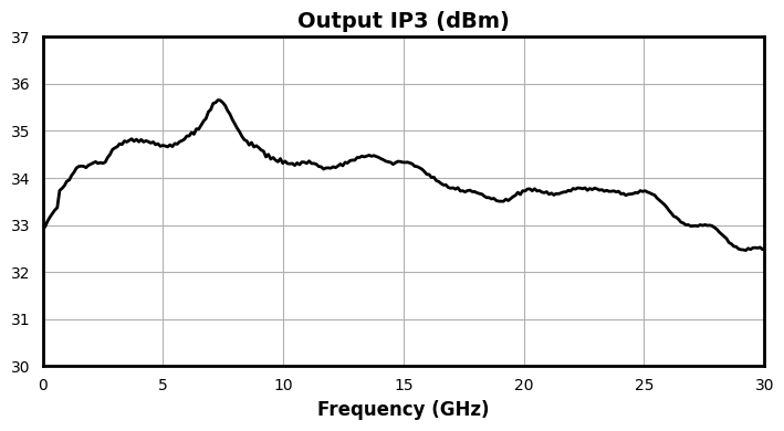
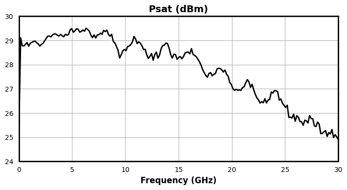
The AMM-11561PSM is a wideband GaAs distributed amplifier covering 0.01 to 30 GHz, delivering 16 dB of small-signal gain, high output power, and linearity. It provides up to +27 dBm saturated output power, with output IP3 up to +33 dBm. Operating from a +12V supply at 230 mA typical current, the amplifier is internally matched to 50 Ω at both the RF input and output ports. These features make it well-suited for wideband driver stages in RF/mmWave front ends, test and measurement instrumentation, electronic warfare, and general-purpose broadband gain block applications.
| Part Number | Description | Package | Green Status | Product Lifecycle | Export Classification |
|---|---|---|---|---|---|
| AMM-11561PSM | 0.01 – 30 GHz High Frequency Distributed Driver Amplifier | Plastic QFN | REACH RoHS | Released | EAR99 |
| EVB-AMM-11561P | Evaluation Board, 0.01-30GHz Surface Mount Amplifier | EVB | REACH RoHS | Released | EAR99 |
| Part Number | Description | Package | Green Status | Product Lifecycle | Export Classification |
|---|---|---|---|---|---|
| AMM-11561PSM | 0.01 – 30 GHz High Frequency Distributed Driver Amplifier | Plastic QFN | REACH RoHS | Released | EAR99 |
| EVB-AMM-11561P | Evaluation Board, 0.01-30GHz Surface Mount Amplifier | EVB | REACH RoHS | Released | EAR99 |
AMM-11561PSM
0.01 – 30 GHz High Frequency Distributed Driver Amplifier
| Revision Code | Revision Date | Comment |
|---|---|---|
| - | 2026-11-19 | Initial Release |
AMM-11561PSM
0.01 – 30 GHz High Frequency Distributed Driver Amplifier
A port diagram of the AMM-11561PSM QFN package is shown below (X-ray view from the top).
| Port | Function | Description | DC Equivalent Circuit |
|---|---|---|---|
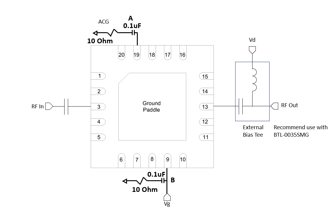
| Pin 9 | Vg | Gate control for the amplifier. The user should apply between -0.15V and -0.35V to Vg pin before applying positive DC voltage to any Vd port. Lower (more negative) voltages on a Vg pin will result in lower drain current and lower small signal gain. | 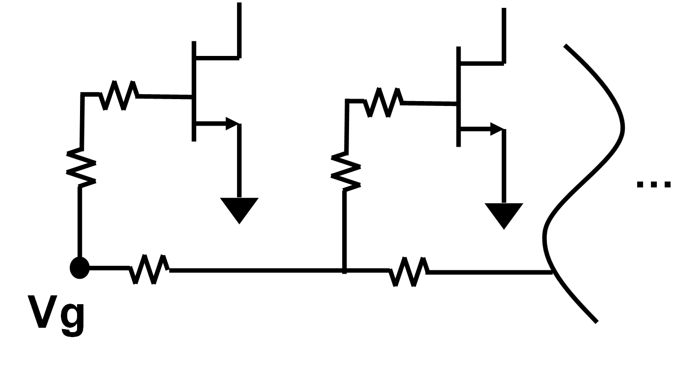 |
| GND | Ground | QFN backside must be connected to a DC/RF ground with high thermal and electrical conductivity. | 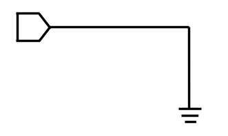 |
| Pin 13 | RF Out / Vd | The RF Out/ Vd pin supplies DC voltage to the drain of the amplifier and also acts as the RF output. This pin requires an external bias-tee. | 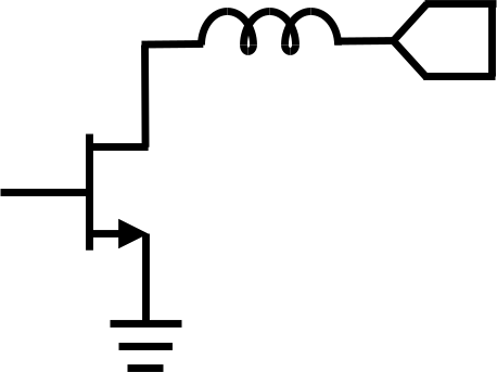 |
| Pin 19 | ACG | The ACG pin provides additional off chip bypass capacitance. A 10 ohm series resistor and 0.1uF chip capacitor is recommended. | 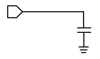 |
| Pin 3 | RF Input | This is the RF input port of the device, and is RF matched to 50 Ω and requires a DC blocking capacitor. | 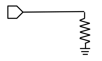 |
AMM-11561PSM
0.01 – 30 GHz High Frequency Distributed Driver Amplifier
The Absolute Maximum Ratings indicate limits beyond which damage may occur to the device. If these limits are exceeded, the device may become inoperable or have a reduced lifetime. This amplifier is designed and characterized in a 50Ω system, and operation in a reflective environment can cause performance degradation.
| Parameter | Maximum Rating | Unit |
|---|---|---|
| Continuous Power Dissipation (PDISS) (at 85 ˚C case temp.) | 3 | W |
| Maximum Operating Temperature | 85 | °C |
| Maximum Storage Temperature | 150 | °C |
| Max Junction Temperature for MTTF of > 1E6 hours | 175 | °C |
| Minimum Operating Temperature | -40 | °C |
| Minimum Storage Temperature | -65 | °C |
| Negative Bias Voltage (Vg) | -2 | V |
| Positive Drain Supply Current (Id) (with RF Input) | 280 | mA |
| Positive Drain Supply Voltage (Vd) | 13 | V |
| RF Input Power | 20 | dBm |
| Thermal Resistance, θJC | 15 | ºC/W |
| Parameter | Details | Rating |
|---|---|---|
| ESD | < 250 Volts | HBM Class 0 |
| Weight | Package name: Plastic QFN | 0.041g |
| Dimensions | - | 4 x 4 mm |
| Moisture Sensitivity Level | - | MSL 1 |
| Parameter | Min | Nominal | Max | Unit |
|---|---|---|---|---|
| Power Supply DC Voltage (Vd) | 10 | 12 | 12 | V |
| Negative Bias Voltage (Vg) | -0.35 | -0.25 | -0.15 | V |
| Ambient Temperature | -40 | 25 | 85 | °C |
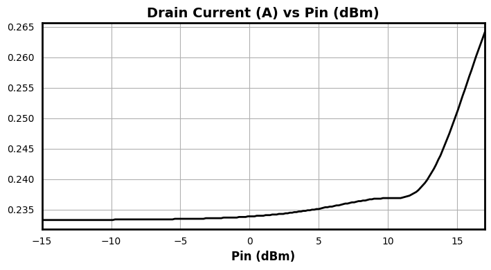
| Power Supply DC Current (Id) (No RF Input) | 150 | 230 | 235 | mA |
| Input Power for Saturation | 10 | 11 | 18 | dBm |
AMM-11561PSM
0.01 – 30 GHz High Frequency Distributed Driver Amplifier
Unless otherwise specified, electrical specifications apply at TA=+25°C, Vd = 12 V, Vg set as required to achieve Id = 230 mA in a 50 Ω system.
| Parameter | Test Conditions | Minimum Frequency (GHz) | Maximum Frequency (GHz) | Min | Typ | Max | Unit |
|---|---|---|---|---|---|---|---|
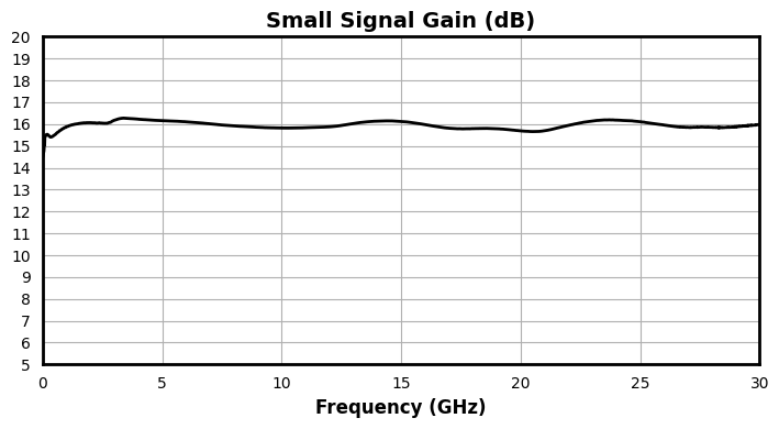
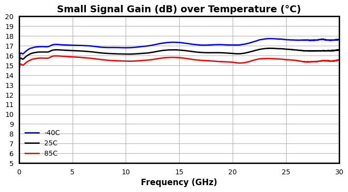
| Small Signal Gain | Pin = -15 dBm | 0.01 | 30 | - | 16.0 | - | dB |
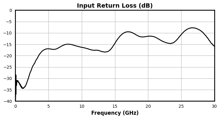
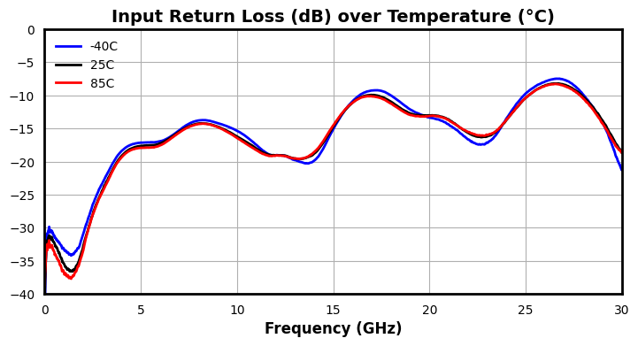
| Input Return Loss | Pin = -15 dBm | 0.01 | 30 | - | 15 | - | dB |
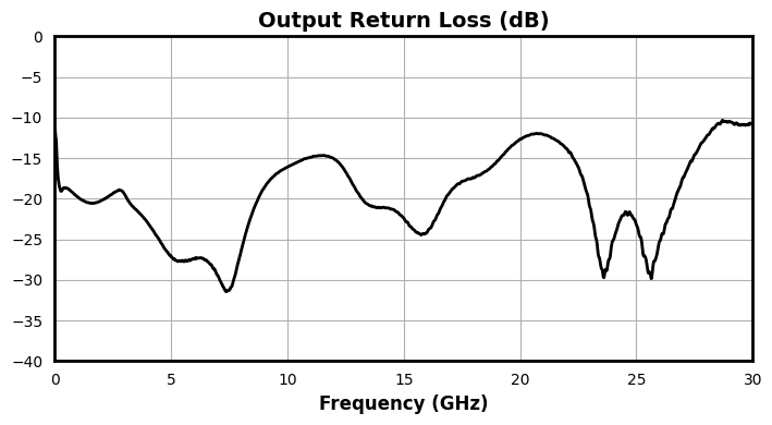
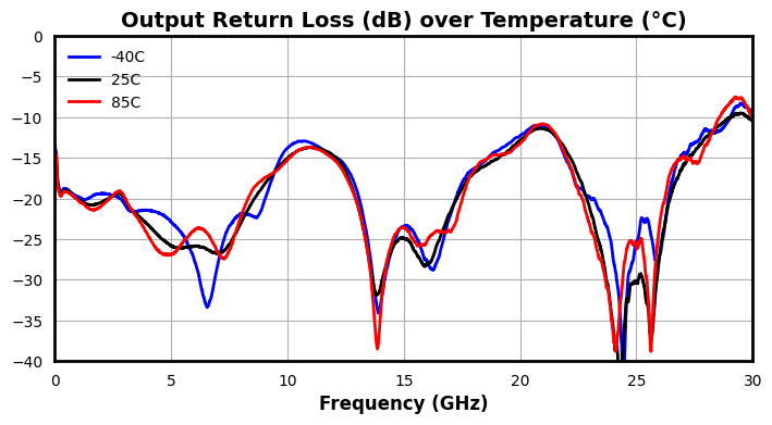
| Output Return Loss | Pin = -15 dBm | 0.01 | 30 | - | 20 | - | dB |
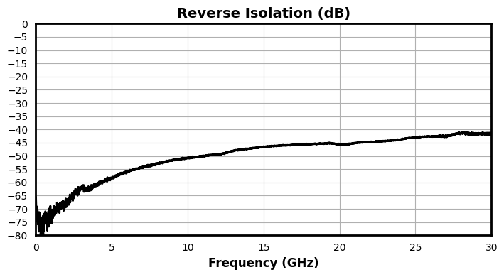
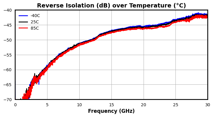
| Reverse Isolation | Pin = -15 dBm | 0.01 | 30 | - | 47 | - | dB |
| Psat | Pin = 17 dBm | 0.01 | 30 | - | 26.67 | - | dBm |
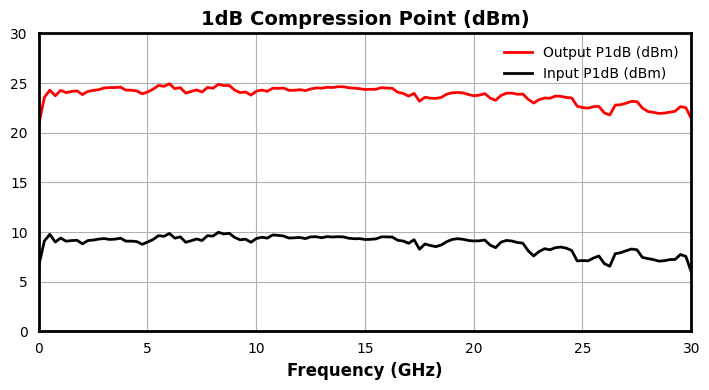
| Input P1dB | - | 0.01 | 30 | - | 8.5 | - | dBm |
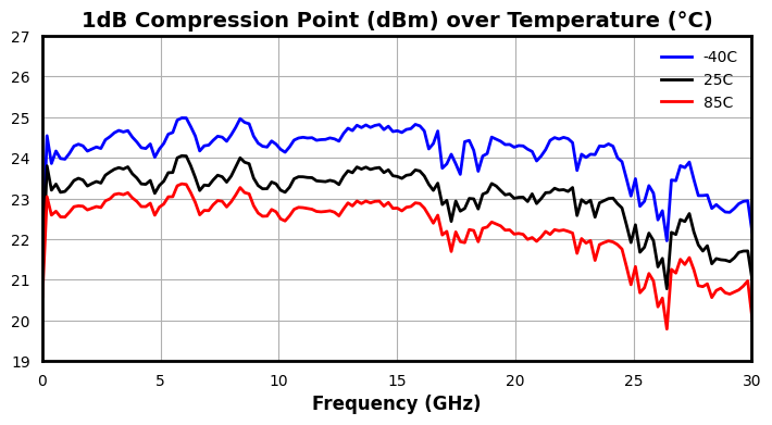
| Output P1dB | - | 0.01 | 30 | - | 23.5 | - | dBm |
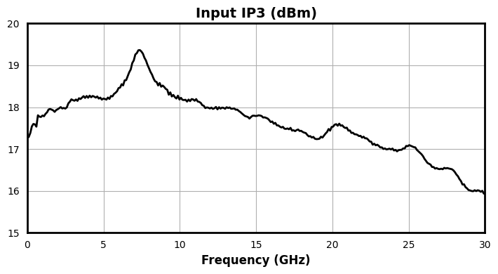
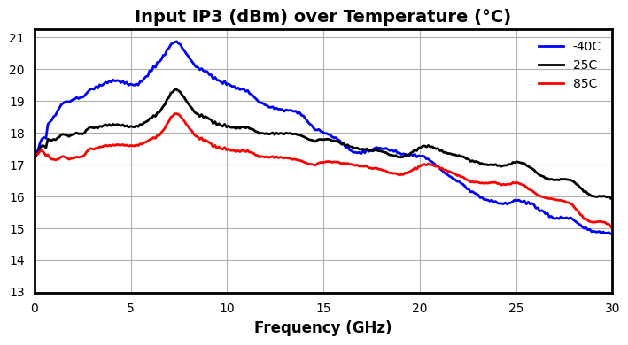
| Input IP3 | Pin = -14 dBm, 1 MHz Tone Spacing | 0.01 | 30 | - | 18 | - | dBm |
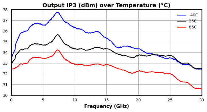
| Output IP3 | Pin = -14 dBm, 1 MHz Tone Spacing | 0.01 | 30 | - | 33 | - | dBm |
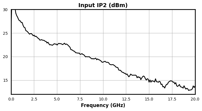
| Input IP2 | Pin = -14 dBm, 1 MHz Tone Spacing | 0.01 | 20 | - | 19 | - | dBm |
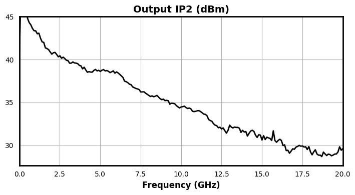
| Output IP2 | Pin = -14 dBm, 1 MHz Tone Spacing | 0.01 | 20 | - | 35 | - | dBm |
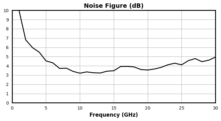
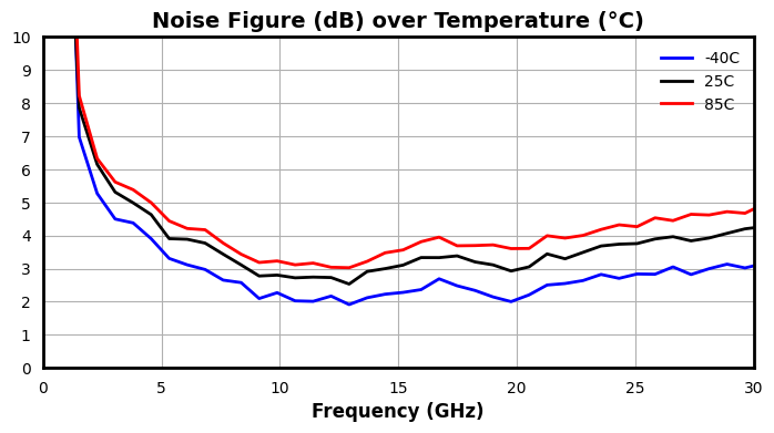
| Noise Figure | Pin = -15 dBm | 0.01 | 30 | - | 3.8 | - | dB |
| Current Consumption | Vd = 12 V, Vg = -0.25 V, no RF input applied | - | - | - | 230 | - | mA |
| Parameter | Test Conditions | Minimum Frequency (GHz) | Maximum Frequency (GHz) | Min | Typ | Max | Unit |
|---|---|---|---|---|---|---|---|
| Small Signal Gain | Pin = -15 dBm | 0.01 | 30 | - | 16.0 | - | dB |
| Input Return Loss | Pin = -15 dBm | 0.01 | 30 | - | 15 | - | dB |
| Output Return Loss | Pin = -15 dBm | 0.01 | 30 | - | 20 | - | dB |
| Reverse Isolation | Pin = -15 dBm | 0.01 | 30 | - | 47 | - | dB |
| Psat | Pin = 17 dBm | 0.01 | 30 | - | 26.67 | - | dBm |
| Input P1dB | - | 0.01 | 30 | - | 8.5 | - | dBm |
| Output P1dB | - | 0.01 | 30 | - | 23.5 | - | dBm |
| Input IP3 | Pin = -14 dBm, 1 MHz Tone Spacing | 0.01 | 30 | - | 18 | - | dBm |
| Output IP3 | Pin = -14 dBm, 1 MHz Tone Spacing | 0.01 | 30 | - | 33 | - | dBm |
| Input IP2 | Pin = -14 dBm, 1 MHz Tone Spacing | 0.01 | 20 | - | 19 | - | dBm |
| Output IP2 | Pin = -14 dBm, 1 MHz Tone Spacing | 0.01 | 20 | - | 35 | - | dBm |
| Noise Figure | Pin = -15 dBm | 0.01 | 30 | - | 3.8 | - | dB |
| Current Consumption | Vd = 12 V, Vg = -0.25 V, no RF input applied | - | - | - | 230 | - | mA |
AMM-11561PSM
0.01 – 30 GHz High Frequency Distributed Driver Amplifier
AMM-11561PSM
0.01 – 30 GHz High Frequency Distributed Driver Amplifier
AMM-11561PSM
0.01 – 30 GHz High Frequency Distributed Driver Amplifier
AMM-11561PSM
0.01 – 30 GHz High Frequency Distributed Driver Amplifier
AMM-11561PSM
0.01 – 30 GHz High Frequency Distributed Driver Amplifier
AMM-11561PSM
0.01 – 30 GHz High Frequency Distributed Driver Amplifier
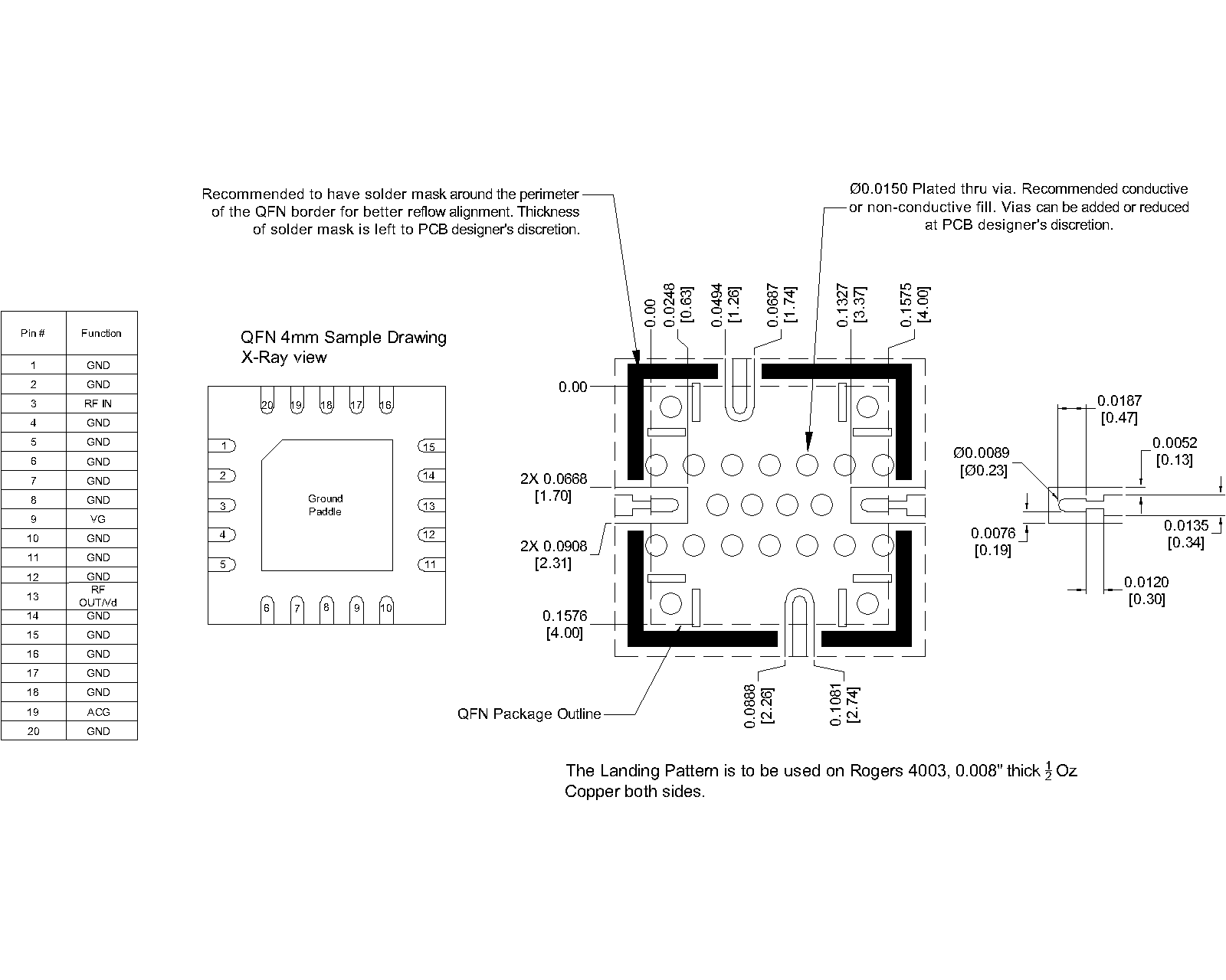
Download : Footprint Drawing
AMM-11561PSM
0.01 – 30 GHz High Frequency Distributed Driver Amplifier