Port Diagram

Sales: 408-778-9952 | General: 408-778-4200 | Fax: 408-778-4300
Sales & Customer Support: [email protected]
Tech Support: [email protected]
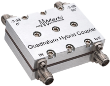
The QH-0R71R3 is an octave band multi-purpose 3dB quadrature (90°) hybrid. It is designed to mate with the MLIQ connectorized package, for use as an image reject downconverter or single sideband upconverter. Custom designs are also available; contact the factory for details.

| Part Number | Description | Connectors | Green Status | Product Lifecycle | Export Classification |
|---|---|---|---|---|---|
| QH-0R71R3 | 3 dB Quadrature Hybrid | Standard | Non-RoHS | Released | EAR99 |
| Part Number | Description | Connectors | Green Status | Product Lifecycle | Export Classification |
|---|---|---|---|---|---|
| QH-0R71R3 | 3 dB Quadrature Hybrid | Standard | Non-RoHS | Released | EAR99 |
QH-0R71R3
3 dB Quadrature Hybrid
QH-0R71R3
3 dB Quadrature Hybrid
| Port | Function | Connector Type | Description | DC Equivalent Circuit |
|---|---|---|---|---|
| GND | Ground | - | Package ground is provided through metal housing and outer coax conductor. |  |
| Port 1 | 90° Output | SMAF | Port 1 is DC short to Port 3 and open to ground. |  |
| Port 2 | 0° Output | SMAF | Port 2 is DC short to Port 4 and open to ground. | |
| Port 3 | Isolated | SMAF | Port 3 is DC short to Port 1 and open to ground. | |
| Port 4 | Input | SMAF | Port 4 is DC short to Port 2 and open to ground. | |
QH-0R71R3
3 dB Quadrature Hybrid
| Parameter | Details | Rating |
|---|---|---|
| Weight | - | 16g |
| Dimensions | - | 27.94 x 16.51 mm |
QH-0R71R3
3 dB Quadrature Hybrid
| Parameter | Test Conditions | Minimum Frequency (GHz) | Maximum Frequency (GHz) | Min | Typ | Max | Unit |
|---|---|---|---|---|---|---|---|
| Amplitude Balance 1 | - | 0.65 | 1.3 | - | 0.3 | 0.7 | dB |
| Excess Insertion Loss 2 | - | 0.65 | 1.3 | - | 0.5 | 1.2 | dB |
| Isolation | - | 0.65 | 1.3 | 13 | 16 | - | dB |
| Mean Coupling | - | 0.65 | 1.3 | - | 3 | - | dB |
| Nominal Phase Shift | - | 0.65 | 1.3 | - | 90 | - | ° |
| Phase Balance | - | 0.65 | 1.3 | - | 3 | 10 | ° |
| VSWR | - | 0.65 | 1.3 | - | 1.3 | - | - |
[1] Maximum amplitude differential is twice the magnitude of the amplitude balance.
[2] Excess Insertion Loss = (Input to Output Insertion Loss) – 3 dB.
QH-0R71R3
3 dB Quadrature Hybrid


QH-0R71R3
3 dB Quadrature Hybrid
