Port Diagram
Only ports 1 and 2 may be used as an input. Ports 3 and 4 are not recommended as inputs. Device is not recommended for applications requiring reflected signals. Ports 1 – 4 correspond to the UA package designation.

Sales: 408-778-9952 | General: 408-778-4200 | Fax: 408-778-4300
Sales & Customer Support: [email protected]
Tech Support: [email protected]
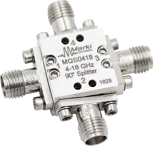
MQS-0418 is a MMIC 4GHz – 18GHz 90° splitter/combiner. Wire bondable 50Ω terminations are available on-chip. Passive GaAs MMIC technology allows production of smaller constructions that replace larger form factor circuit board constructions. Tight fabrication tolerances allow for less unit to unit variation than traditional splitter/combiner technologies. The MQS-0418 is available as a wire bondable chip and connectorized module. Low variation allows for accurate simulations using the provided S4P file taken from measured production units. The MQS-0418 is not recommended for applications involving reflected signals.

| Part Number | Description | Package | Connectors | Green Status | Product Lifecycle | Export Classification |
|---|---|---|---|---|---|---|
| MQS-0418UA | MMIC 4-18GHz 90° Splitter / Combiner | UA | Standard | REACH RoHS | Released | EAR99 |
| Part Number | Description | Package | Connectors | Green Status | Product Lifecycle | Export Classification |
|---|---|---|---|---|---|---|
| MQS-0418UA | MMIC 4-18GHz 90° Splitter / Combiner | UA | Standard | REACH RoHS | Released | EAR99 |
MQS-0418UA
MMIC 4-18GHz 90° Splitter / Combiner
| Revision Code | Revision Date | Comment |
|---|---|---|
| - | 2018-08-01 | Datasheet Initial Release |
MQS-0418UA
MMIC 4-18GHz 90° Splitter / Combiner
Only ports 1 and 2 may be used as an input. Ports 3 and 4 are not recommended as inputs. Device is not recommended for applications requiring reflected signals. Ports 1 – 4 correspond to the UA package designation.
| Port | Function | Connector Type | Description | DC Equivalent Circuit |
|---|---|---|---|---|
| GND | Ground | - | Package ground provided through metal housing and outer coax conductor. |  |
| Port 1 | Input 1 | SMAF | Port 1 is DC short to port 3 and open to ground. |  |
| Port 2 | 90° Output 2 | SMAF | Port 2 is DC short to port 4 and open to ground. | |
| Port 3 | 0° Output 3 | SMAF | Port 3 is DC short to port 1 and open to ground. | |
| Port 4 | Isolated 4 | - | Port 4 is DC short to port 2 and open to ground. | |
[1][2][3][4] Each configuration describes a different application of the same product.
MQS-0418UA
MMIC 4-18GHz 90° Splitter / Combiner
| Port | Function | Connector Type | Description | DC Equivalent Circuit |
|---|---|---|---|---|
| GND | Ground | - | Package ground provided through metal housing and outer coax conductor. | |
| Port 1 | 90° Output 1 | SMAF | Port 1 is DC short to port 3 and open to ground. | |
| Port 2 | Input 2 | SMAF | Port 2 is DC short to port 4 and open to ground. | |
| Port 3 | Isolated 3 | SMAF | Port 3 is DC short to port 1 and open to ground. | |
| Port 4 | 0° Output 4 | SMAF | Port 4 is DC short to port 2 and open to ground. | |
[1][2][3][4] Each configuration describes a different application of the same product.
MQS-0418UA
MMIC 4-18GHz 90° Splitter / Combiner
| Parameter | Maximum Rating | Unit |
|---|---|---|
| Maximum Operating Temperature | 100 | °C |
| Maximum Storage Temperature | 125 | °C |
| Minimum Operating Temperature | -55 | °C |
| Minimum Storage Temperature | -65 | °C |
| Parameter | Details | Rating |
|---|---|---|
| Dimensions | - | 14.22 x 14.22 mm |
MQS-0418UA
MMIC 4-18GHz 90° Splitter / Combiner
The electrical specifications apply at TA=+25°C in a 50Ω system. Min and Max limits are guaranteed at TA=+25°C.
| Parameter | Port Configuration | Test Conditions | Minimum Frequency (GHz) | Maximum Frequency (GHz) | Min | Typ | Max | Unit |
|---|---|---|---|---|---|---|---|---|
| Mean Coupling | A | - | 4 | 18 | - | 3 | - | dB |
| Amplitude Balance | - | - | 4 | 18 | - | 0.4 | 2 | dB |
| Excess Insertion Loss | - | - | 4 | 18 | - | 1.9 | 3.8 | dB |
| Impedance | - | - | 4 | 18 | - | 50 | - | Ω |
| Isolation | - | - | 4 | 18 | 10 | 20 | - | dB |
| Nominal Phase Shift | - | - | 4 | 18 | - | 90 | - | ° |
| Phase Balance | - | - | 4 | 18 | - | 1.5 | 9 | ° |
| VSWR | - | - | 4 | 18 | - | 1.13 | - | - |
MQS-0418UA
MMIC 4-18GHz 90° Splitter / Combiner
Phase balance spread is shown due to large performance spread. Minimal variance observed in amplitude balance and insertion loss. Performance spread is related to packaging and bond wire inductance variation.


MQS-0418UA
MMIC 4-18GHz 90° Splitter / Combiner


MQS-0418UA
MMIC 4-18GHz 90° Splitter / Combiner
