Port Diagram

Sales: 408-778-9952 | General: 408-778-4200 | Fax: 408-778-4300
Sales & Customer Support: [email protected]
Tech Support: [email protected]
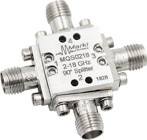
The MQS-0218 is a MMIC 2GHz – 18GHz 90° splitter/combiner. Wire bondable 50Ω terminations are available on-chip. Passive GaAs MMIC technology allows production of smaller constructions that replace larger form factor circuit board constructions. Tight fabrication tolerances allow for less unit to unit variation than traditional splitter/combiner technologies. The MQS-0218 is available as a wire bondable chip and connectorized module. Low variation allows for accurate simulations using the provided S4P file taken from measured production units.The MQS-0218 is not recommended for applications involving reflected signals.

| Part Number | Description | Package | Connectors | Green Status | Product Lifecycle | Export Classification |
|---|---|---|---|---|---|---|
| MQS-0218UA | MMIC 2-18GHz 90° Splitter / Combiner | UA | Standard | REACH RoHS | Released | EAR99 |
| Part Number | Description | Package | Connectors | Green Status | Product Lifecycle | Export Classification |
|---|---|---|---|---|---|---|
| MQS-0218UA | MMIC 2-18GHz 90° Splitter / Combiner | UA | Standard | REACH RoHS | Released | EAR99 |
MQS-0218UA
MMIC 2-18GHz 90° Splitter / Combiner
| Revision Code | Revision Date | Comment |
|---|---|---|
| - | 2018-08-01 | Datasheet Initial Release |
MQS-0218UA
MMIC 2-18GHz 90° Splitter / Combiner
| Port | Function | Connector Type | Description | DC Equivalent Circuit |
|---|---|---|---|---|
| GND | Ground | - | Package ground provided through metal housing and outer coax conductor. |  |
| Port 1 | Input | SMAF | Port 1 is DC short to port 3 and open to ground. |  |
| Port 2 | 90° Output | SMAF | Port 2 is DC short to port 4 and open to ground. | |
| Port 3 | 0° Output | SMAF | Port 3 is DC short to port 1 and open to ground. | |
| Port 4 | Isolated | SMAF | Port 4 is DC short to port 2 and open to ground. | |
MQS-0218UA
MMIC 2-18GHz 90° Splitter / Combiner
| Port | Function | Connector Type | Description | DC Equivalent Circuit |
|---|---|---|---|---|
| GND | Ground | - | Package ground provided through metal housing and outer coax conductor. | |
| Port 1 | 90° Output | SMAF | Port 1 is DC short to port 3 and open to ground | |
| Port 2 | Input | SMAF | Port 2 is DC short to port 4 and open to ground....... | |
| Port 3 | Isolated | SMAF | Port 3 is DC short to port 1 and open to ground. | |
| Port 4 | 0° Output | SMAF | Port 4 is DC short to port 2 and open to ground. | |
MQS-0218UA
MMIC 2-18GHz 90° Splitter / Combiner
The Absolute Maximum Ratings indicate limits beyond which damage may occur to the device. If these limits are exceeded, the device may be inoperable or have a reduced lifetime.
| Parameter | Maximum Rating | Unit |
|---|---|---|
| Maximum Operating Temperature | 100 | °C |
| Maximum Storage Temperature | 125 | °C |
| Minimum Operating Temperature | -55 | °C |
| Minimum Storage Temperature | -65 | °C |
| RF Power Handling | 10 | W |
| Parameter | Details | Rating |
|---|---|---|
| Dimensions | - | 14.22 x 14.22 mm |
MQS-0218UA
MMIC 2-18GHz 90° Splitter / Combiner
The electrical specifications apply at TA=+25°C in a 50Ω system. Min and Max limits are guaranteed at TA=+25°C.
| Parameter | Port Configuration | Test Conditions | Minimum Frequency (GHz) | Maximum Frequency (GHz) | Min | Typ | Max | Unit |
|---|---|---|---|---|---|---|---|---|
| Amplitude Balance | A | - | 2 | 3 | - | 2 | - | dB |
| Amplitude Balance | A | - | 3 | 18 | - | 1 | 5 | dB |
| Excess Insertion Loss | A | - | 2 | 18 | - | 1.4 | 4.2 | dB |
| Impedance | A | - | 2 | 18 | - | 50 | - | Ω |
| Isolation | A | - | 2 | 18 | 9 | 18 | - | dB |
| Mean Coupling | A | - | 2 | 18 | - | 3 | - | dB |
| Nominal Phase Shift | A | - | 2 | 18 | - | 90 | - | ° |
| Phase Balance | A | - | 17 | 18 | - | 6 | - | ° |
| Phase Balance | A | - | 2 | 17 | - | 3 | 12 | ° |
| VSWR | A | - | 2 | 18 | - | 1.17 | - | - |
| Amplitude Balance | B | - | 2 | 3 | - | 2 | - | dB |
| Amplitude Balance | B | - | 3 | 18 | - | 1 | 5 | dB |
| Excess Insertion Loss | B | - | 2 | 18 | - | 1.4 | 4.2 | dB |
| Impedance | B | - | 2 | 18 | - | 50 | - | Ω |
| Isolation | B | - | 2 | 18 | 9 | 18 | - | dB |
| Mean Coupling | B | - | 2 | 18 | - | 3 | - | dB |
| Nominal Phase Shift | B | - | 2 | 18 | - | 90 | - | ° |
| Phase Balance | B | - | - | 2 | 17 | 3 | 12 | ° |
| Phase Balance | B | - | 17 | 18 | - | 6 | - | ° |
| VSWR | B | - | 2 | 18 | - | 1.17 | - | - |
MQS-0218UA
MMIC 2-18GHz 90° Splitter / Combiner


MQS-0218UA
MMIC 2-18GHz 90° Splitter / Combiner


MQS-0218UA
MMIC 2-18GHz 90° Splitter / Combiner
