Rev: - | Copyright © 2018 Marki Microwave LLC.

General Description

The MQS-0209 is a MMIC 2GHz – 9GHz 90° splitter/combiner. Wire bondable 50Ω terminations are available on-chip. Passive GaAs MMIC technology allows production of smaller constructions that replace larger form factor circuit board constructions. Tight fabrication tolerances allow for less unit to unit variation than traditional splitter/combiner technologies. The MQS-0209 is available as a wire bondable chip or connectorized module. Low variation allows for accurate simulations using the provided S4P file taken from measured production units. The MQS-0209 is not recommended for applications involving reflected signals

Features

  • Designed for S and C-band applications
  • High amplitude and phase balance
  • High isolation
  • Low insertion loss
  • On-chip 50Ω load terminations

Functional Block Diagram

Block Diagram

Electrical Performance Summary

ParameterTypUnit
Frequency Range2 to 9GHz
Isolation 16dB
Nominal Phase Shift 90°
Phase Balance 3°
Amplitude Balance 0.3dB

Summary only – refer to the Electrical Specifications, Absolute Maximum Ratings, and Recommended Operating Range tables for complete details.

Part Ordering Options

Part NumberDescriptionPackageConnectorsGreen StatusProduct LifecycleExport Classification
MQS-0209UBMMIC 2-9GHz 90° Splitter / CombinerUBStandard

REACH

RoHS

ReleasedEAR99

Table Of Contents

Typical Performance Plots

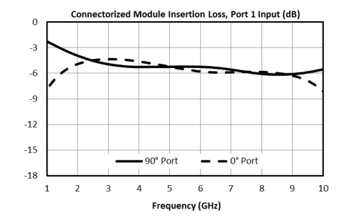
Connectorized Module Insertion Loss, Port 1 Input (dB) graph for MQS-0209UB
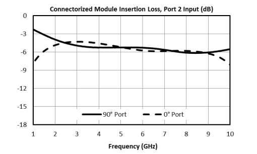
Connectorized Module Insertion Loss, Port 2 Input(dB) graph for MQS-0209UB
Connectorized Module Amplitude Balance, Port 1 Input (dB) graph for MQS-0209UB
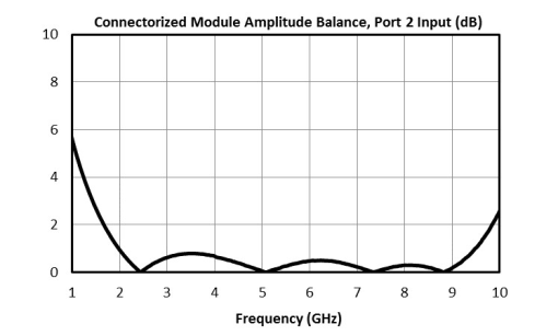
Connectorized Module Amplitude Balance,Port 2 Input(dB) graph for MQS-0209UB
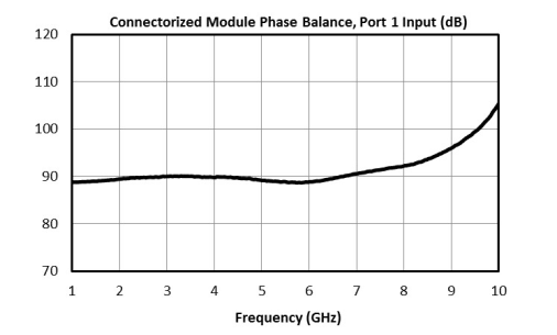
Connectorized Module Phase Balance, Port 1 input(dB) graph for MQS-0209UB
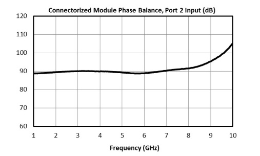
Connectorized Module Phase Balance, Port 2 Input(dB) graph for MQS-0209UB
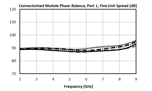
Connectorized Module Phase Balance, Port 1, Five Unit Spread (dB) graph for MQS-0209UB
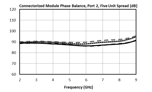
Connectorized Module Phase Balance, Port 2, Five Unit Spread (dB) graph for MQS-0209UB
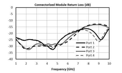
Connectorized Module Return Loss (dB) graph for MQS-0209UB
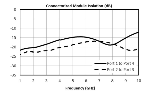
Connectorized Module Isolation (dB) graph for MQS-0209UB

Specifications

Electrical Specifications

The electrical specifications apply at TA=+25°C in a 50Ω system. Min and Max limits are guaranteed at TA=+25°C.

ParameterPort ConfigurationTest ConditionsMinimum
Frequency
(GHz)
Maximum
Frequency
(GHz)
MinTypMaxUnit
Frequency Range--2 9---GHz
Amplitude Balance A-2 9-0.312dB
Excess Insertion Loss A-2 9-2.55.2dB
Impedance A-2 9-50-Ω
Isolation A-2 9916-dB
Mean Coupling A-2 9-3-dB
Nominal Phase Shift A-2 9-90-°
Phase Balance A-2 9-310°
VSWR A-2 9-1.13--

Absolute Maximum Ratings

The Absolute Maximum Ratings indicate limits beyond which damage may occur to the device. If these limits are exceeded, the device may be inoperable or have a reduced lifetime.

ParameterMaximum RatingUnit
Maximum Operating Temperature 100°C
Maximum Storage Temperature 125°C
Minimum Operating Temperature -55°C
Minimum Storage Temperature -65°C
RF Power Handling 10W

Package Information

ParameterDetailsRating
Dimensions-16.26 x 16.26 mm

Port Configuration and Functions

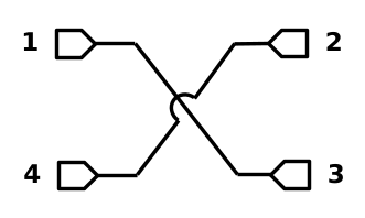
Port Diagram

Diagram of the port configuration for MQS-0209UB

Port Functions

Configuration A

PortFunctionConnector TypeDescriptionDC Equivalent
Circuit
Port 1Input SMAFPort 1 is DC short to port 3 and open to ground.Equivalent circuit for the Input
Port 290° Output SMAFPort 2 is DC short to port 4 and open to ground.Equivalent circuit for the 90° Output
Port 30° Output SMAFPort 3 is DC short to port 1 and open to ground.Equivalent circuit for the 0° Output
Port 4Isolated SMAFPort 4 is DC short to port 2 and open to ground.Equivalent circuit for the Isolated

Configuration B

PortFunctionConnector TypeDescriptionDC Equivalent
Circuit
Port 190° Output SMAFPort 1 is DC short to port 3 and open to ground.Equivalent circuit for the 90° Output
Port 2Input SMAFPort 2 is DC short to port 4 and open to ground.Equivalent circuit for the Input
Port 3Isolated SMAFPort 3 is DC short to port 1 and open to ground.Equivalent circuit for the Isolated
Port 40° Output SMAFPort 4 is DC short to port 2 and open to ground.Equivalent circuit for the 0° Output

Operation

Application Information

Quadrature signal generation is useful for many applications in analog signal processing. Marki MQH/S MMIC quadrature hybrids and 90˚ Splitter/Combiners offer this functionality in a small factor with high repeatability. Below are applications and how they can be realized with the MQH and MQS product lines.

Quadrature Hybrids vs 90˚ Splitter/Combiners

Some products are ‘true’ quadrature hybrids, while others are 90˚ Splitter/Combiners. A quadrature hybrid is symmetric about all four ports, meaning that in a splitting application any port can be used as an input, with the isolated and output ports following from this selection. Likewise, for a combining application, any port can be used as an output.
A 90˚ Splitter/Combiner is not symmetric. When splitting, only ports 1 and 2 can be used as an input. If ports 3 or 4 were used, there would be significant phase walk-off between the output ports. As a combiner, only ports 1 and 2 are suitable as output ports. The phase walk-off introduced when using ports 3 or 4 as an output means that reflected signals recombine and cancel poorly inside a 90° Splitter/Combiner.

Single Sideband and Image Reject Mixers
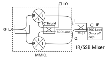
Mqs 0209 Ub Single Sideband

The primary application for the MQH and MQS series is as IF or LO quadrature signal splitter/combiners. They can be used in combination with the MMIQ series of IQ mixers to create broadband single sideband and image reject mixers. Either 90˚ Splitter/Combiners or quadrature hybrids can be used as the IF hybrid, but if a 90˚ Splitter/Combiner is used only one sideband (or image) is accessible, whereas if a quadrature hybrid is used than both sidebands are accessible. If a 90˚ Splitter/Combiner is used for a single sideband upconverter or image reject mixer, port 1 (or 2) should be used as the IF input/output and ports 2 and 3 (or 1 and 4) should be connected to the I and Q ports. Selecting port 1 or 2 to terminate will select which sideband of the mixer to reject.

Balanced Amplifiers

In a balanced amplifier, the poor return loss of an amplifier is compensated for with a quadrature hybrid. In this application, the reflections from the input or output are collected at the isolated port of the quadrature hybrid and terminated.Since a 90˚ Splitter/Combiner is not completely symmetric, reflected signals will not terminate as well as with a quadrature hybrid. An MQH option is recommended for this application. If a 90˚ Splitter/Combiner is used for a single sideband upconverter or image reject mixer, port 1 (or 2) should be used as the IF input/output and ports 2 and 3 (or 1 and 4) should be connected to the I and Q ports. Selecting port 1 or 2 to terminate will select which sideband of the mixer to reject. Testing/simulation is recommended when considering if a 90° Splitter/Combiner is suitable.
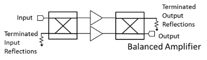
Mqs 0209 Ub Balanced Amplifiers

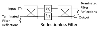
Reflectionless Filter

Mqs 0209 Ub Reflectionless Filter

Similar to a balanced amplifier, a reflectionless filter will terminate reflections that are out of band for a filter (but in band for the quadrature hybrid) at the isolated port. Since a 90˚ Splitter/Combiner is not completely symmetric, reflected signals will not terminate as well as with a quadrature hybrid. An MQH option is recommended for this application.

If a 90˚Splitter/Combiner is used for a single sideband upconverter or image reject mixer, port 1 (or 2) should be used as the IF input/output and ports 2 and 3 (or 1 and 4) should be connected to the I and Q ports. Selecting port 1 or 2 to terminate will select which sideband of the mixer to reject. Testing/simulation is recommended when considering if a 90° Splitter/Combiner is suitable.

Reflective Applications

Mqs 0209 Ub Reflective Applications

Unlike in the previous applications, reflective applications only work well with a quadrature hybrid (not a 90˚ Splitter/Combiner). In these applications a signal is reflected off of two identical structures (typically a PIN diode) and the output signal is collected at the isolated port. In this case the desired signal is deliberately reflected. Since a 90˚ Splitter/Combiner is not completely symmetric, you will have poor results if you use these for reflective applications.

Mechanical Data

Outline Drawing

Download : Outline 2D Drawing Outline 3D Drawing Outline 3D STP

Outline Drawing

Revision History

Revision CodeRevision DateComment
-2018-08-01Datasheet Initial Release

DISCLAIMER

MARKI MICROWAVE, LLC., (“MARKI”) PROVIDES TECHNICAL SPECIFICATIONS AND DATA (INCLUDING DATASHEETS), APPLICATION OR OTHER DESIGN ADVICE, WEB TOOLS, AND OTHER INFORMATION AND RESOURCES “AS IS” AND WITH ALL FAULTS. MARKI DISCLAIMS ALL WARRANTIES, EXPRESS OR IMPLIED, INCLUDING, WITHOUT LIMITATION, ANY IMPLIED WARRANTIES OF MERCHANTABILITY, FITNESS FOR A PARTICULAR PURPOSE, OR NON-INFRINGEMENT.

These resources are intended for developers skilled in the art designing with Marki products. You are solely responsible for (1) selecting the appropriate products for your application, (2) designing, validating, and testing your application, and (3) ensuring your application meets applicable standards and other requirements. Marki makes no guarantee regarding the suitability of its products for any particular purpose, nor does Marki assume any liability whatsoever arising out of your use or application of any Marki product.

Marki grants you permission to use these resources only for development of an application that uses Marki products. Other reproduction or use of these resources is strictly prohibited. No license is granted to any other Marki intellectual property or to any third-party intellectual property. Marki reserves the right to make changes to the product(s) or information contained herein without notice.

MARKI MICROWAVE, M wave logo, FastSwitch, and T3 MIXER are trademarks or registered trademarks of Marki Microwave, LLC. All other trademarks used are the property of their respective owners.

© 2018, Marki Microwave, LLC