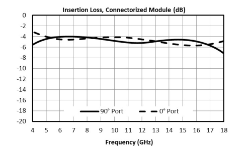
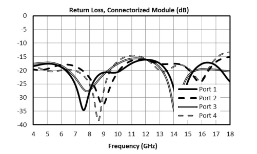
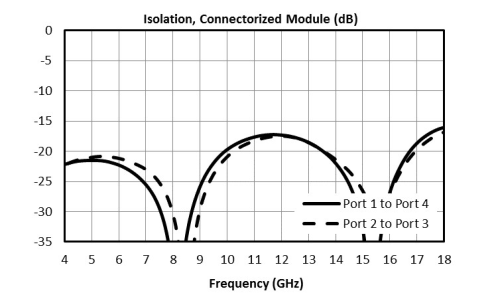
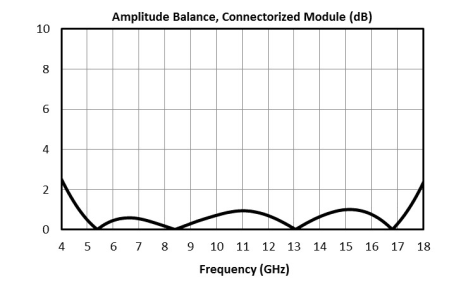
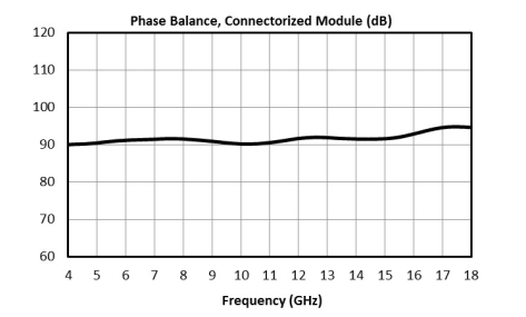
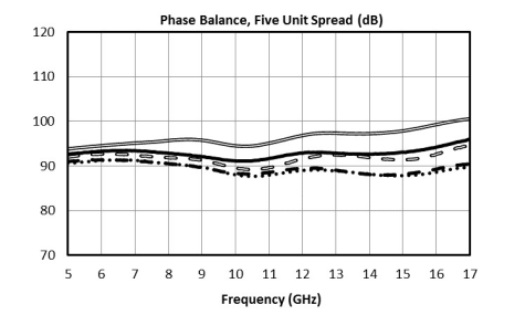
Quadrature signal generation is useful for many applications in analog signal processing. Marki MQH/S MMIC quadrature hybrids and 90˚ Splitter/Combiners offer this functionality in a small factor with high repeatability. Below are applications and how they can be realized with the MQH and MQS product lines.
Quadrature Hybrids vs 90˚ Splitter/Combiners
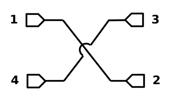
Some products are ‘true’ quadrature hybrids, while others are 90˚ Splitter/Combiners. A quadrature hybrid is symmetric about all four ports, meaning that in a splitting application any port can be used as an input, with the isolated and output ports following from this selection. Likewise, for a combining application, any port can be used as an output.
A 90˚ Splitter/Combiner is not symmetric. When splitting, only ports 1 and 2 can be used as an input. If ports 3 or 4 were used, there would be significant phase walk-off between the output ports. As a combiner, only ports 1 and 2 are suitable as output ports. The phase walk-off introduced when using ports 3 or 4 as an output means that reflected signals recombine and cancel poorly inside a 90° Splitter/Combiner.
Single Sideband and Image Reject Mixers

The primary application for the MQH and MQS series is as IF or LO quadrature signal splitter/combiners. They can be used in combination with the MMIQ series of IQ mixers to create broadband single sideband and image reject mixers. Either 90˚ Splitter/Combiners or quadrature hybrids can be used as the IF hybrid, but if a 90˚ Splitter/Combiner is used only one sideband (or image) is accessible, whereas if a quadrature hybrid is used than both sidebands are accessible.
If a 90˚ Splitter/Combiner is used for a single sideband upconverter or image reject mixer, port 1 (or 2) should be used as the IF input/output and ports 2 and 3 (or 1 and 4) should be connected to the I and Q ports. Selecting port 1 or 2 to terminate will select which sideband of the mixer to reject.
Balanced Amplifiers
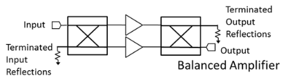
In a balanced amplifier, the poor return loss of an amplifier is compensated for with a quadrature hybrid. In this application, the reflections from the input or output are collected at the isolated port of the quadrature hybrid and terminated.
Since a 90˚ Splitter/Combiner is not completely symmetric, reflected signals will not terminate as well as with a quadrature hybrid. An MQH option is recommended for this application. Testing/simulation is recommended when considering if a 90° Splitter/Combiner is suitable
Reflectionless Filter
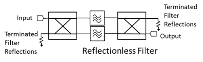
Similar to a balanced amplifier, a reflectionless filter will terminate reflections that are out of band for a filter (but in band for the quadrature hybrid) at the isolated port.
Since a 90˚ Splitter/Combiner is not completely symmetric, reflected signals will not terminate as well as with a quadrature hybrid. An MQH option is recommended for this application. Testing/simulation is recommended when considering if a 90° Splitter/Combiner is suitable.
Reflective Applications
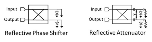 Unlike in the previous applications, reflective applications only work well with a quadrature hybrid (not a 90˚ Splitter/Combiner). In these applications a signal is reflected off of two identical structures (typically a PIN diode) and the output signal is collected at the isolated port. In this case the desired signal is deliberately reflected.
Since a 90˚ Splitter/Combiner is not completely symmetric, you will have poor results if you use one for reflective applications.