Absolute Maximum Ratings
| Parameter | Maximum Rating | Unit |
|---|---|---|
| RF Power Handling as a Power Combiner | 1 | W |
| RF Power Handling as a Power Divider | 10 | W |
Sales: 408-778-9952 | General: 408-778-4200 | Fax: 408-778-4300
Sales & Customer Support: [email protected]
Tech Support: [email protected]
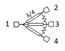
3-Way Wilkinson power dividers can be used for both in-phase power splitting and power combining applications. These power dividers feature the lowest insertion loss (ideally 4.77 dB 3-way splitting loss), excellent amplitude and phase balance, and high isolation across the entire operating band.
N/A
| Part Number | Description | Connectors | Green Status | Product Lifecycle | Export Classification |
|---|---|---|---|---|---|
| PD3-0R412 | 3-Way Wilkinson Power Divider | Standard | REACH RoHS | Released | EAR99 |
| Part Number | Description | Connectors | Green Status | Product Lifecycle | Export Classification |
|---|---|---|---|---|---|
| PD3-0R412 | 3-Way Wilkinson Power Divider | Standard | REACH RoHS | Released | EAR99 |
PD3-0R412
3-Way Wilkinson Power Divider
| Revision Code | Revision Date | Comment |
|---|---|---|
| - | 2012-11-13 | Initial Date Released |
| A | 2025-12-17 | Power Handling Updated |
PD3-0R412
3-Way Wilkinson Power Divider
| Port | Function | Connector Type | Description | DC Equivalent Circuit |
|---|---|---|---|---|
| In | Divider Common Input | SMAF | Wilkinson Divider Common Input | - |
| Out 1 | Divider Output 1 | SMAF | RF divided output 1 of the Wilkinson divider. | - |
| Out 2 | Divider Output 2 | SMAF | RF divided output 2 of the Wilkinson divider. | - |
| Out 3 | Divider Output 3 | SMAF | RF divided output 3 of the Wilkinson divider. | - |
PD3-0R412
3-Way Wilkinson Power Divider
| Parameter | Maximum Rating | Unit |
|---|---|---|
| RF Power Handling as a Power Combiner | 1 | W |
| RF Power Handling as a Power Divider | 10 | W |
| Parameter | Details | Rating |
|---|---|---|
| Weight | - | 86g |
| Dimensions | - | 167.13 x 20.32mm |
PD3-0R412
3-Way Wilkinson Power Divider
Specifications guaranteed from -55 to +100°C, measured in a 50Ω system.
| Parameter | Test Conditions | Minimum Frequency (GHz) | Maximum Frequency (GHz) | Min | Typ | Max | Unit |
|---|---|---|---|---|---|---|---|
| Amplitude Balance | - | 0.4 | 12 | - | 0.1 | 0.5 | dB |
| Excess Insertion Loss 1 | - | 0.4 | 12 | - | 1.5 | 3 | dB |
| Nominal Phase Shift | - | 0.4 | 12 | - | 0 | - | ° |
| Nominal Power Splitting | - | 0.4 | 12 | - | 4.77 | - | dB |
| Phase Balance | - | 0.4 | 12 | - | 2 | 10 | ° |
| VSWR | - | 0.6 | 12 | - | 1.3 | 1.55 | - |
| VSWR | - | 0.4 | 0.6 | - | 1.5 | - | - |
| Isolation | - | 0.6 | 12 | 15 | 25 | - | dB |
| Isolation | - | 0.4 | 0.6 | 12 | - | - | dB |
[1] Excess Insertion Loss = (Input Port to Common Port Insertion Loss) - 6dB
PD3-0R412
3-Way Wilkinson Power Divider


PD3-0R412
3-Way Wilkinson Power Divider
