Absolute Maximum Ratings
| Parameter | Maximum Rating | Unit |
|---|---|---|
| RF Power Handling as a Power Combiner | 1 | W |
| RF Power Handling as a Power Divider | 10 | W |
Sales: 408-778-9952 | General: 408-778-4200 | Fax: 408-778-4300
Sales & Customer Support: [email protected]
Tech Support: [email protected]
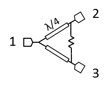
2-Way Wilkinson power dividers can be used for both in-phase power splitting and power combining applications. These power dividers feature the lowest insertion loss (ideally 3 dB splitting loss), excellent amplitude and phase balance, and high isolation across the entire operating band. High isolation can be critically important for power combining applications, such as when performing accurate intermodulation distortion (IMD) tests.

N/A
| Part Number | Description | Connectors | Green Status | Product Lifecycle | Export Classification |
|---|---|---|---|---|---|
| PD-0440 | Wideband Wilkinson Power Divider | Standard | REACH RoHS | Released | EAR99 |
| Part Number | Description | Connectors | Green Status | Product Lifecycle | Export Classification |
|---|---|---|---|---|---|
| PD-0440 | Wideband Wilkinson Power Divider | Standard | REACH RoHS | Released | EAR99 |
PD-0440
Wideband Wilkinson Power Divider
| Revision Code | Revision Date | Comment |
|---|---|---|
| - | 2019-12-23 | Initial Date Release |
| G0 | 2025-12-17 | Power Handling Updated |
PD-0440
Wideband Wilkinson Power Divider
| Port | Function | Connector Type | Description | DC Equivalent Circuit |
|---|---|---|---|---|
| In | Divider Common Input | - | Wilkinson Divider Common input | - |
| Out 1 | Divider Output 1 | - | RF Divided Output 1 of the Wilkinson Divider | - |
| Out 2 | Divider Output 2 | - | RF Divided Output 2 of the Wilkinson Divider | - |
PD-0440
Wideband Wilkinson Power Divider
| Parameter | Maximum Rating | Unit |
|---|---|---|
| RF Power Handling as a Power Combiner | 1 | W |
| RF Power Handling as a Power Divider | 10 | W |
| Parameter | Details | Rating |
|---|---|---|
| Weight | - | 35g |
| Dimensions | - | 16.51 x 26.04 mm |
PD-0440
Wideband Wilkinson Power Divider
Specifications guaranteed from -55 to +100°C, measured in a 50Ω system.
| Parameter | Test Conditions | Minimum Frequency (GHz) | Maximum Frequency (GHz) | Min | Typ | Max | Unit |
|---|---|---|---|---|---|---|---|
| Amplitude Balance | - | 4 | 40 | - | 0.2 | 0.75 | dB |
| Excess Insertion Loss 1 | - | 4 | 40 | - | 1 | 2 | dB |
| Isolation | - | 4 | 40 | 13 | 18 | - | dB |
| Nominal Phase Shift | - | 4 | 40 | - | 0 | - | ° |
| Nominal Power Splitting | - | 4 | 40 | - | 3 | - | dB |
| Phase Balance | - | 4 | 40 | - | 3 | 12 | ° |
| VSWR | - | 4 | 40 | - | 1.4 | - | - |
[1] Excess Insertion Loss = (Input Port to Common Port Insertion Loss) - 3dB
PD-0440
Wideband Wilkinson Power Divider


PD-0440
Wideband Wilkinson Power Divider
