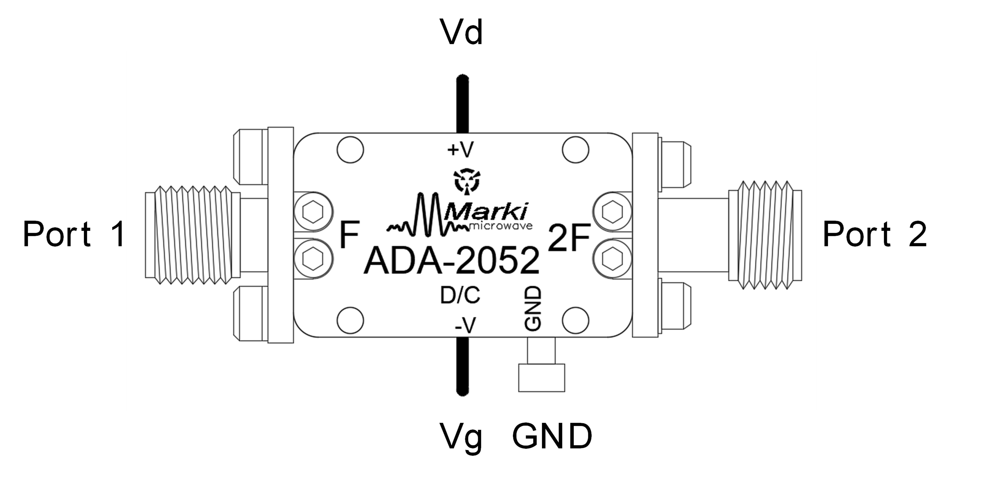
Port Diagram
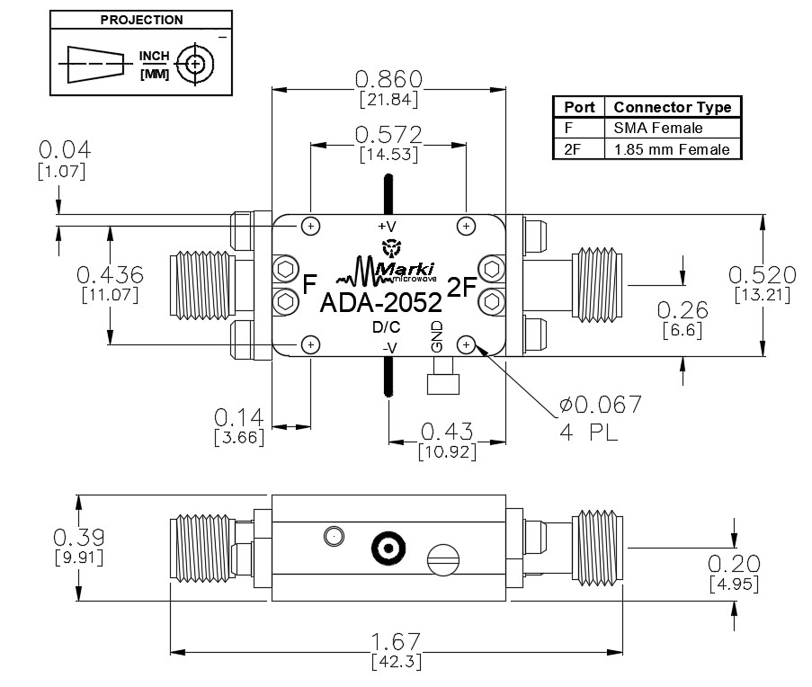
A top-down view of the ADA-2052 outline drawing is shown below.
Sales: 408-778-9952 | General: 408-778-4200 | Fax: 408-778-4300
Sales & Customer Support: [email protected]
Tech Support: [email protected]
The ADA-2052 can be used as a frequency extender to enhance the frequency range of a <26 GHz synthesizer up to 52 GHz. Useful for lab testing, test and measurement, and prototype systems. It consists of an input buffer ADM-5974CH amplifier, MMD 2060HCH doubler, and output buffer AMM 6702CH amplifier to provide a +16 dBm output (suitable for driving most mixers) from a -6 to +2 dBm input.

N/A

| Part Number | Description | Connectors | Green Status | Product Lifecycle | Export Classification |
|---|---|---|---|---|---|
| ADA-2052 | Amplifier/Doubler/Amplifier | Standard | REACH RoHS | Released | EAR99 |
| Part Number | Description | Connectors | Green Status | Product Lifecycle | Export Classification |
|---|---|---|---|---|---|
| ADA-2052 | Amplifier/Doubler/Amplifier | Standard | REACH RoHS | Released | EAR99 |
ADA-2052
Amplifier/Doubler/Amplifier
| Revision Code | Revision Date | Comment |
|---|---|---|
| - | 2019-02-01 | Datasheet Initial Release |
| A | 2020-01-01 | Added Sequencing Requirements |
| B | 2020-06-01 | Updated Outline Drawing and Port Diagram |
| C | 2020-08-01 | Updated Chipset Information |
| D | 2022-08-01 | Updated Frequency Coverage |
| E | 2026-02-13 | MTTF Table Added. |
ADA-2052
Amplifier/Doubler/Amplifier
A top-down view of the ADA-2052 outline drawing is shown below.
| Port | Function | Connector Type | Description | DC Equivalent Circuit |
|---|---|---|---|---|
| GND | Ground | - | Ground path is provided through the metal housing and outer ground lug. |  |
| Port 1 | Input | SMAF | This pin is DC open and matched to 50 Ω at frequency range 10.5 - 26 GHz. |  |
| Port 2 | Output | 1.85F | This pin is DC open and matched to 50 Ω at frequency range 21 – 52 GHz. | |
| Vd | Positive bias | - | Drain bias port must be connected to a 3.5 – 5.0 Volt power supply. |  |
| Vg | Negative bias | - | Gate control for the amplifier must be connected to a -0.5 to -0.6 Volt power supply. |  |
ADA-2052
Amplifier/Doubler/Amplifier
The Absolute Maximum Ratings indicate limits beyond which damage may occur to the device. If these limits are exceeded, the device may be inoperable or have a reduced lifetime.
| Parameter | Maximum Rating | Unit |
|---|---|---|
| Maximum Operating Temperature | 85 | °C |
| Maximum Storage Temperature | 150 | °C |
| Minimum Operating Temperature | -55 | °C |
| Minimum Storage Temperature | -65 | °C |
| Negative Bias Current | 2 | mA |
| Negative Bias Voltage | -2 | V |
| Positive Bias Current | 550 | mA |
| Positive Bias Voltage | 5 | V |
| Power Dissipation | 2.5 | W |
| RF Input Power | 20 | dBm |
| T (°C) | λ (TIF) | MTTF (hr) | MTTF (yr) |
|---|---|---|---|
| 105 | 2,441.45 | 4.10E+05 | 47 |
| 85 | 310.48 | 3.22E+06 | 368 |
| 55 | 8.79 | 1.14E+08 | 12,992 |
| 25 | 0.12 | 8.24E+09 | 941,063 |
| Parameter | Details | Rating |
|---|---|---|
| ESD | 250 to < 500 Volts | HBM Class 1A |
| Dimensions | - | 21.84 x 13.21 mm |
| Parameter | Min | Nominal | Max | Unit |
|---|---|---|---|---|
| Gate Bias DC Voltage (Vg) | -0.6 | -0.5 | - | V |
| Positive DC Voltage (Vd) | 3.5 | 5 | - | V |
ADA-2052
Amplifier/Doubler/Amplifier
The electrical specifications apply at TA=+25°C in a 50Ω system. Suppression is relative to doubled output power. Isolation is defined as relative to the fundamental input power.
| Parameter | Test Conditions | Minimum Frequency (GHz) | Maximum Frequency (GHz) | Min | Typ | Max | Unit |
|---|---|---|---|---|---|---|---|
| Current Consumption 1 | Vd: +4V | - | - | - | 400 | - | mA |
| Current Consumption 2 | Vg: -0.5V | - | - | - | 0 | - | mA |
| Input Power | Input = 10.5 - 26.0 GHz | - | - | -6 | 0 | - | dBm |
| Output Converted Power, 2F (out) | Output = 21.0 - 52.0 GHz | - | - | 14 | 16 | - | dBm |
| Suppression, 1F | Output = 10.5 - 26.0 GHz | - | - | - | 30 | - | dBc |
| Suppression, 3F | Output = 31.5 - 60.0 GHz | - | - | - | 26 | - | dBc |
| Input Frequency Range | - | - | - | 10.5 | - | 26 | GHz |
| Output Frequency Range | - | - | - | 21 | - | 52 | GHz |
[1] It is required that the negative bias be applied before or concurrent with the positive bias. The higher input power the better 2F output power and the worse 1F suppression will be, (see plot 2F Output Converted Power).
[2] It is required that the negative bias be applied before or concurrent with the positive bias.
ADA-2052
Amplifier/Doubler/Amplifier


ADA-2052
Amplifier/Doubler/Amplifier