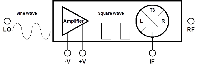
Port Diagram
Sales: 408-778-9952 | General: 408-778-4200 | Fax: 408-778-4300
Sales & Customer Support: [email protected]
Tech Support: [email protected]
The T3A-07PA is a versatile, robust, and broadband Two-Tone-Terminator mixer integrated with a sub 10 ps risetime square wave amplifier. The T3A-07PA employs the most sophisticated mixer on the market today and offers unparalleled performance when compared to all other mixer technologies. The T3A-07PA delivers exceptional IMD suppression with low conversion loss.

N/A
| Part Number | Description | Package | Connectors | Green Status | Product Lifecycle | Export Classification |
|---|---|---|---|---|---|---|
| T3A-07PA | Two-Tone-Terminator Mixer/LO-Amplifier | PA | Standard | Released | EAR99 |
| Part Number | Description | Package | Connectors | Green Status | Product Lifecycle | Export Classification |
|---|---|---|---|---|---|---|
| T3A-07PA | Two-Tone-Terminator Mixer/LO-Amplifier | PA | Standard | Released | EAR99 |
T3A-07PA
Two-Tone-Terminator Mixer/LO-Amplifier
| Revision Code | Revision Date | Comment |
|---|---|---|
| - | 2022-07-01 | Initial Release |
T3A-07PA
Two-Tone-Terminator Mixer/LO-Amplifier
| Port | Function | Connector Type | Description | DC Equivalent Circuit |
|---|---|---|---|---|
| IF | IF | SMAF | The IF port is DC blocked and AC matched to 50 Ohms from 1 MHz to 4 GHz. |  |
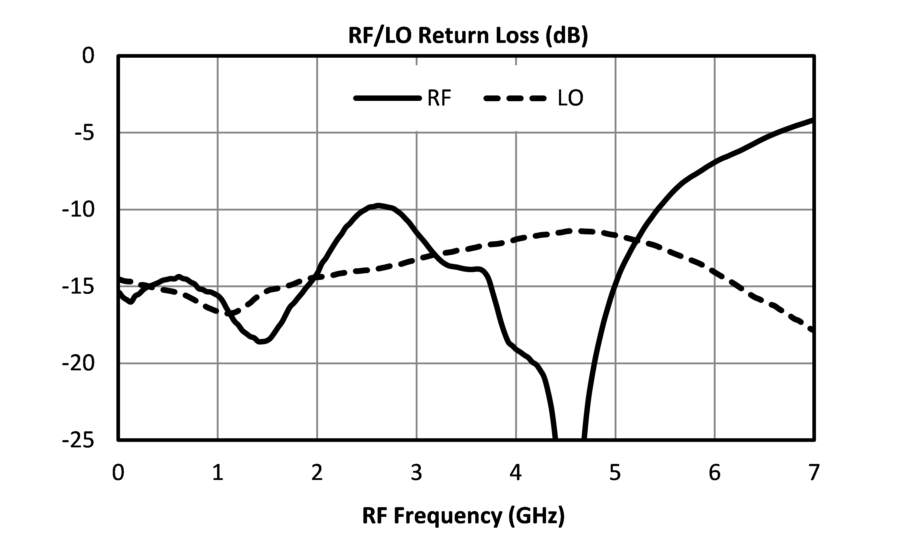
| LO | LO | SMAF | The LO port is DC blocked and AC matched to 50 Ohms from 10 MHz to 7 GHz. |  |
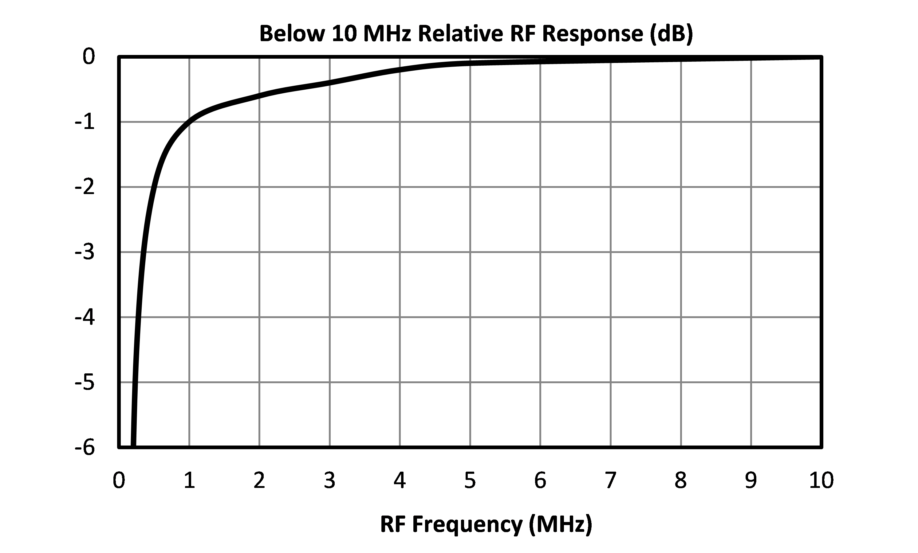
| RF | RF | SMAF | The RF port is DC short to ground and AC matched to 50 Ohms from 10 MHz to 7 GHz. Blocking capacitor is optional. |  |
T3A-07PA
Two-Tone-Terminator Mixer/LO-Amplifier
| Parameter | Maximum Rating | Unit |
|---|---|---|
| LO Power Handling | 17 | dBm |
| Maximum Operating Temperature | 70 | °C |
| Maximum Storage Temperature | 125 | °C |
| Minimum Operating Temperature | 0 | °C |
| Minimum Storage Temperature | -65 | °C |
| RF DC Current | 1 | Amp |
| RF Power Handling | 25 | dBm |
| Parameter | Details | Rating |
|---|---|---|
| ESD | < 250 Volts | HBM Class 0 |
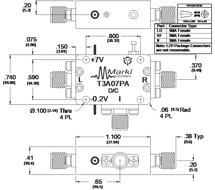
| Dimensions | - | 20.32 x 18.80 mm |
| Parameter | Min | Nominal | Max | Unit |
|---|---|---|---|---|
| Positive Supply Current 1 | - | 250 | 300 | mA |
| Negative Supply Current 2 | - | - | 0.5 | mA |
| LO Input Power | 10 | - | 15 | - |
[1] +5.0 Volts DC (+7 V max)
[2] 0 to -0.2 Volts DC
T3A-07PA
Two-Tone-Terminator Mixer/LO-Amplifier
Specifications guaranteed from 0 to +70°C, measured in a 50Ω system.
| Parameter | Test Conditions | Min | Typ | Max | Unit |
|---|---|---|---|---|---|
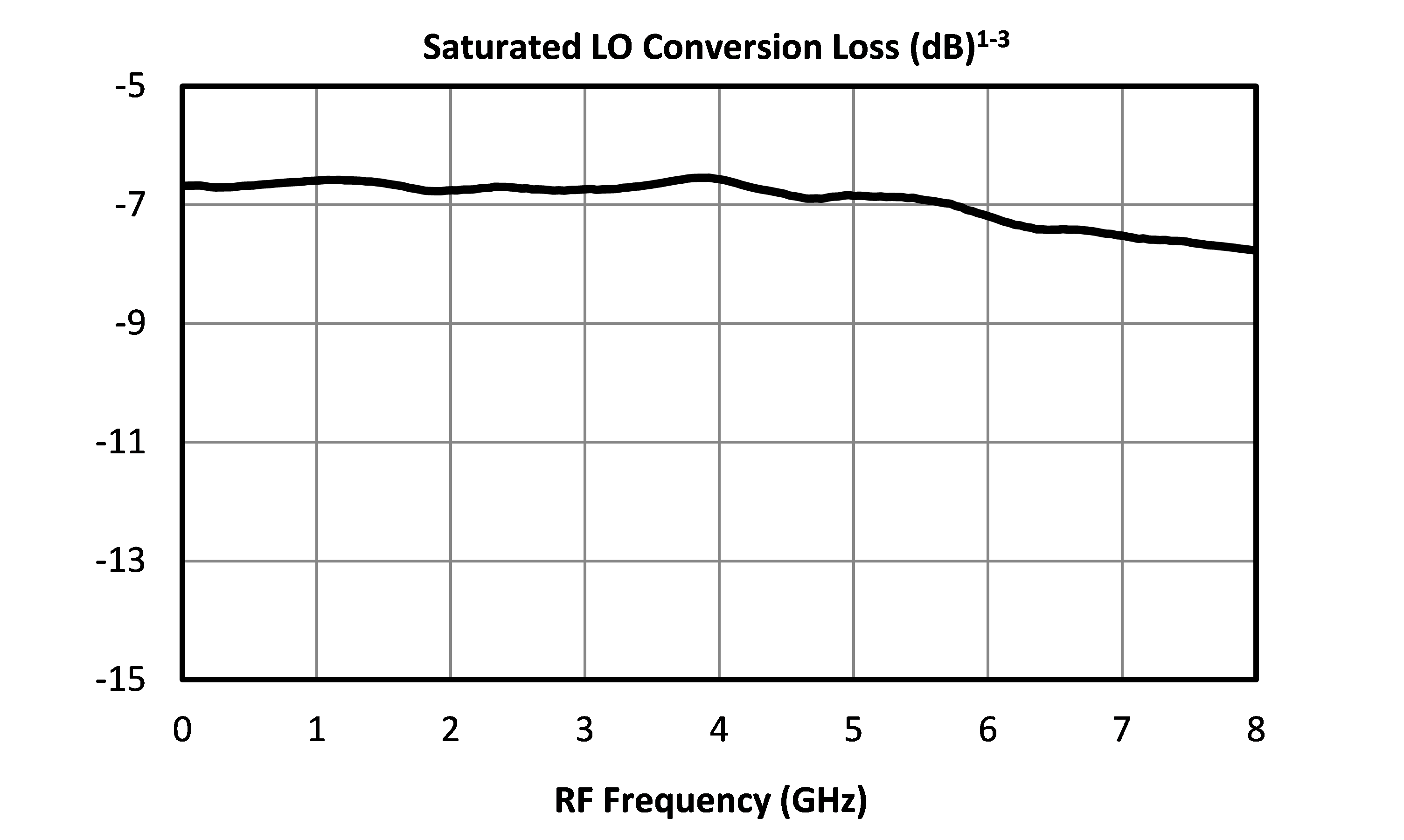
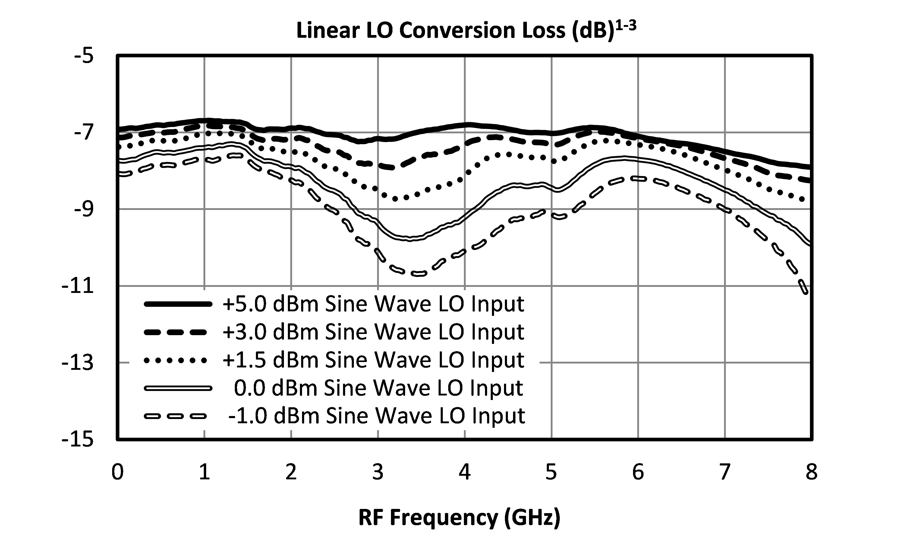
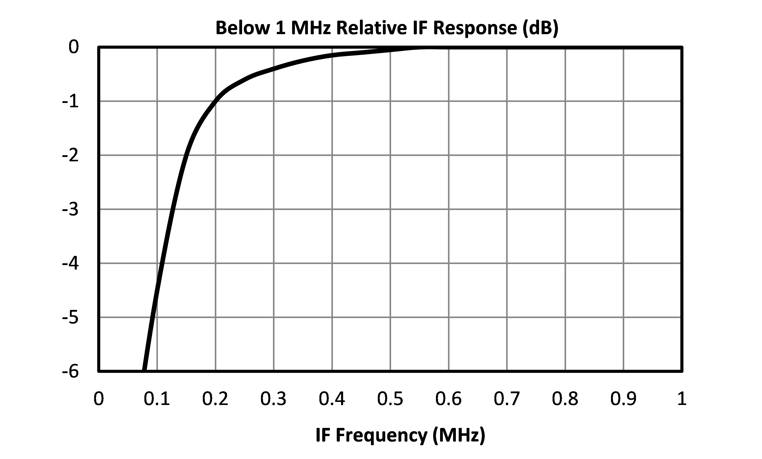
| Conversion Loss | LO/RF=0.01-7 GHz IF=.001-0.5 GHz | - | 6.5 | 9 | dB |
| Conversion Loss | LO/RF=0.01-7 GHz IF=.001-4.0 GHz | - | 8 | 10.5 | dB |
| Current Consumption | +5.0 Volts DC (+7 V max) | - | 250 | 300 | mA |
| Current Consumption | Gate Current, Ig 0 to -0.2 Volts DC | - | - | 0.5 | mA |
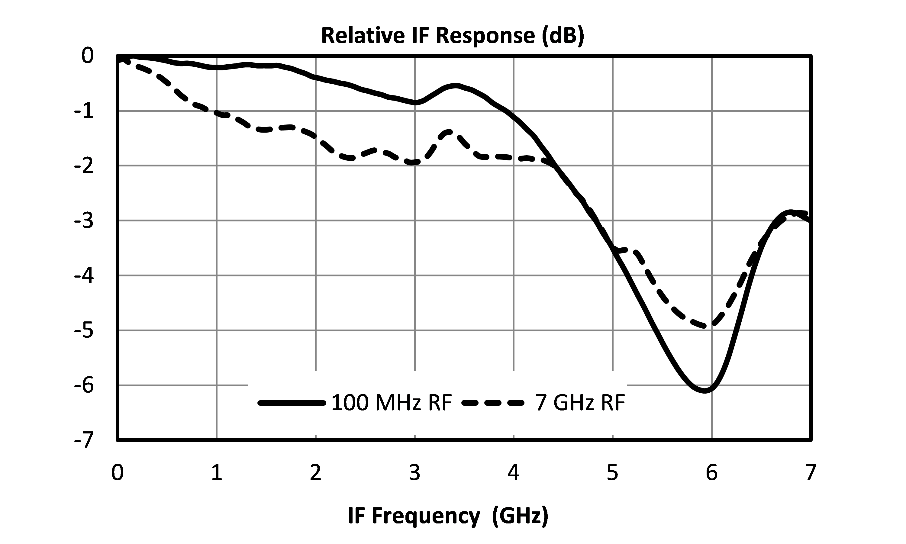
| IF Frequency Range | - | 0.001 | - | 4 | GHz |
| Input P1dB | LO/RF=0.01-7 GHz | - | 16 | - | dBm |
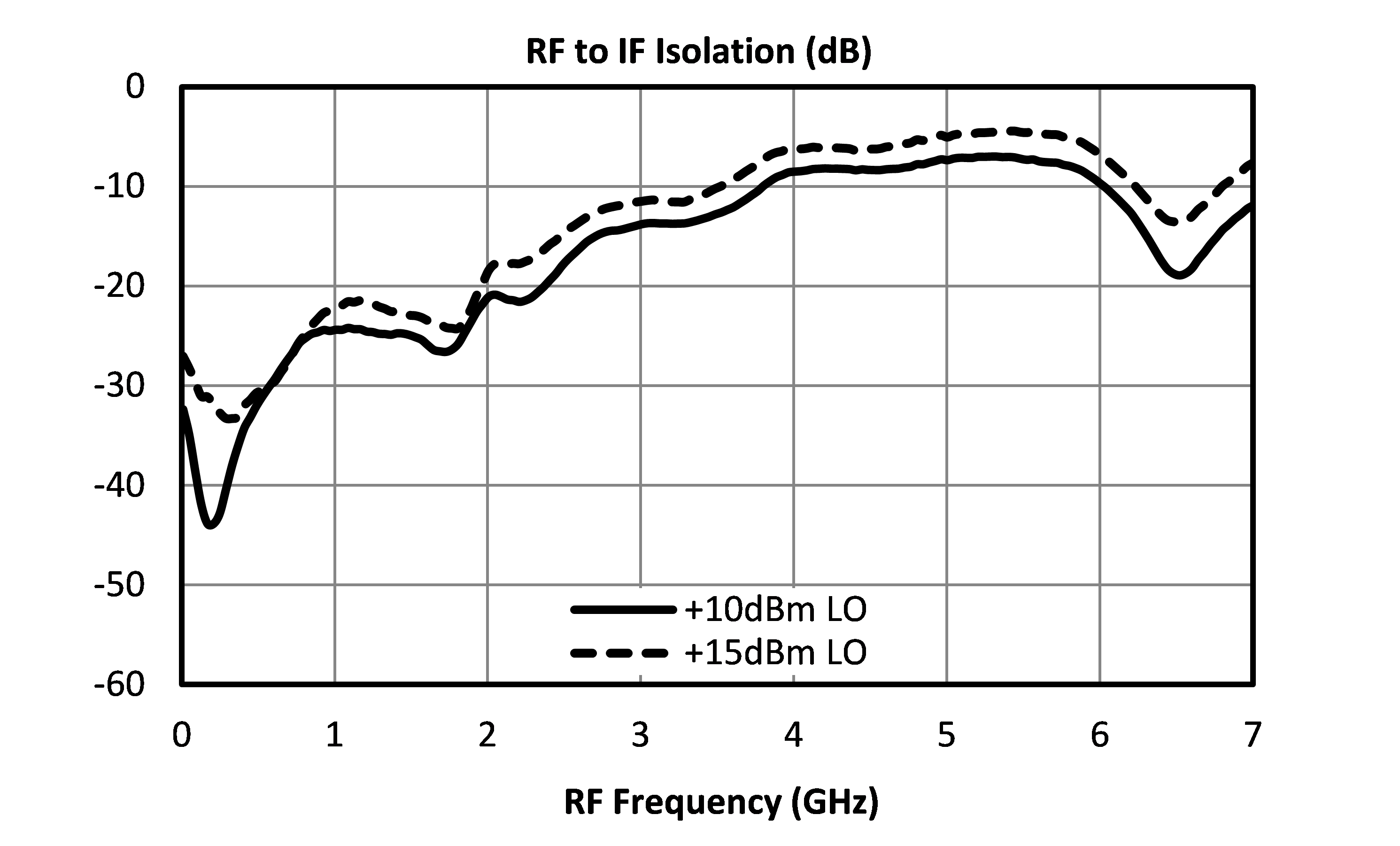
| LO Drive Level (Square wave) | - | 10 | - | 15 | dBm |
| LO Frequency Range | - | 0.01 | - | 7 | GHz |
| RF Frequency Range | - | 0.01 | - | 7 | GHz |
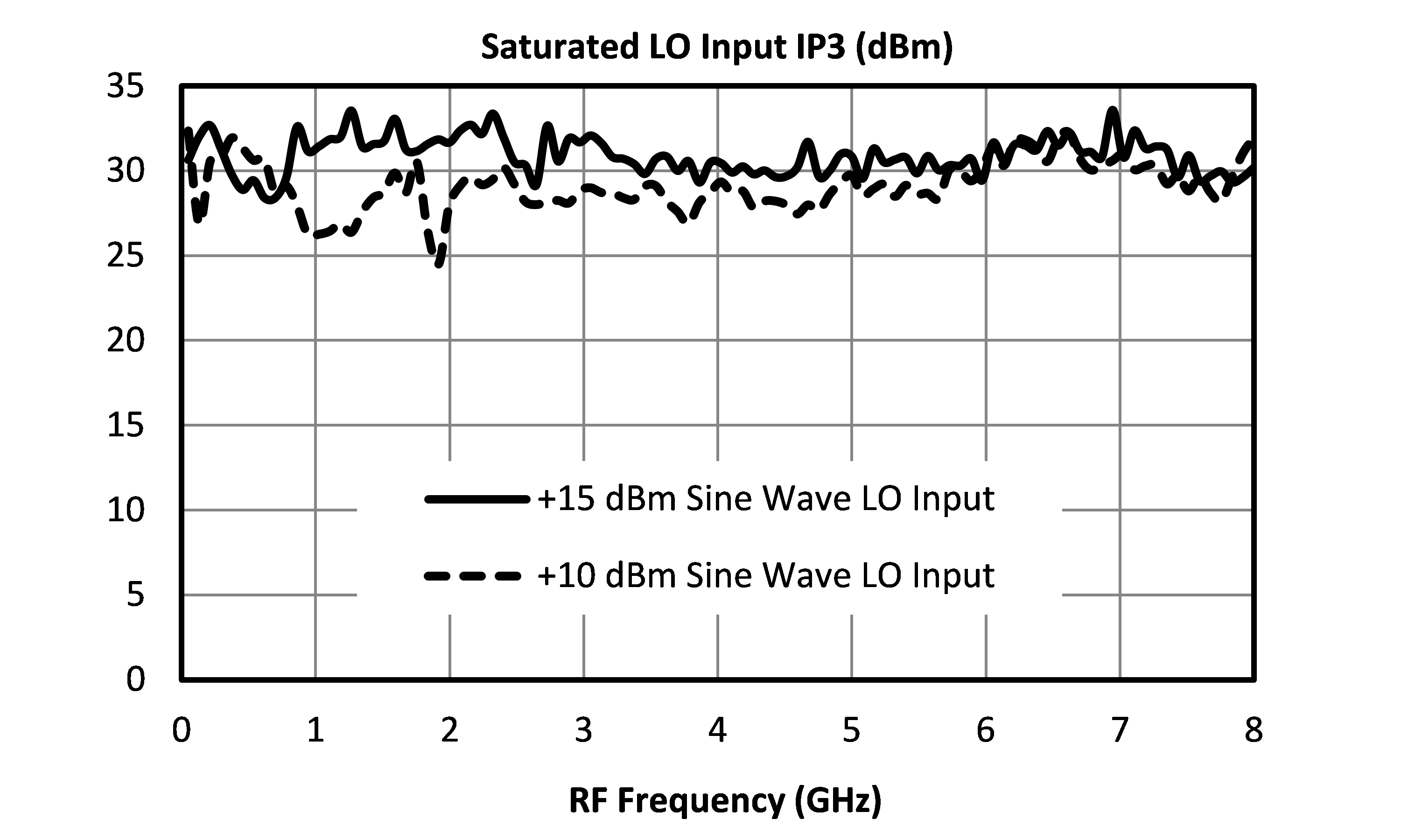
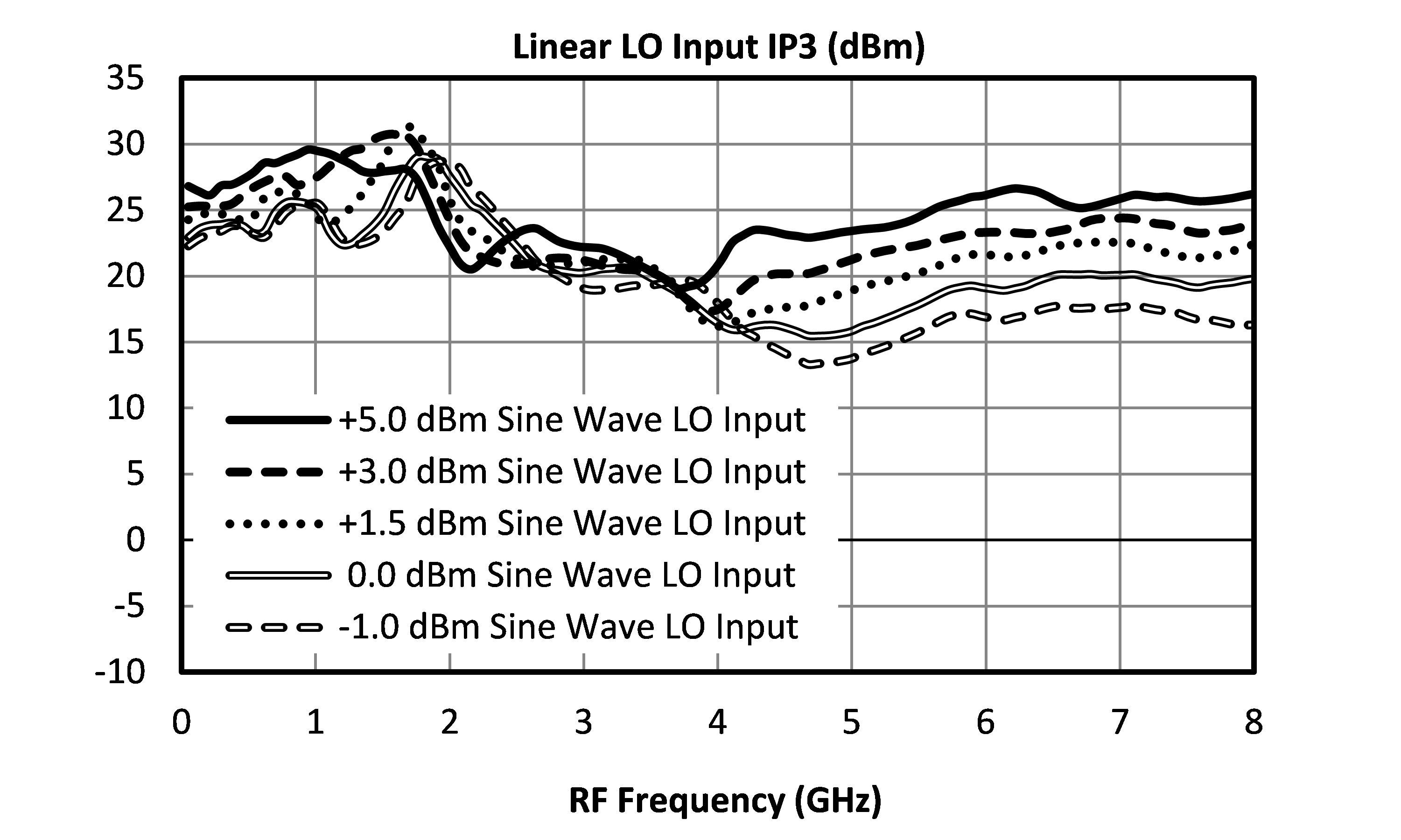
| Input IP3 | - | - | 31 | - | dBm |
| Parameter | Test Conditions | Min | Typ | Max | Unit |
|---|---|---|---|---|---|
| Conversion Loss | LO/RF=0.01-7 GHz IF=.001-0.5 GHz | - | 6.5 | 9 | dB |
| Conversion Loss | LO/RF=0.01-7 GHz IF=.001-4.0 GHz | - | 8 | 10.5 | dB |
| Current Consumption | +5.0 Volts DC (+7 V max) | - | 250 | 300 | mA |
| Current Consumption | Gate Current, Ig 0 to -0.2 Volts DC | - | - | 0.5 | mA |
| IF Frequency Range | - | 0.001 | - | 4 | GHz |
| Input P1dB | LO/RF=0.01-7 GHz | - | 16 | - | dBm |
| LO Drive Level (Square wave) | - | 10 | - | 15 | dBm |
| LO Frequency Range | - | 0.01 | - | 7 | GHz |
| RF Frequency Range | - | 0.01 | - | 7 | GHz |
| Input IP3 | - | - | 31 | - | dBm |
T3A-07PA
Two-Tone-Terminator Mixer/LO-Amplifier
T3A-07PA
Two-Tone-Terminator Mixer/LO-Amplifier
T3A-07PA
Two-Tone-Terminator Mixer/LO-Amplifier
