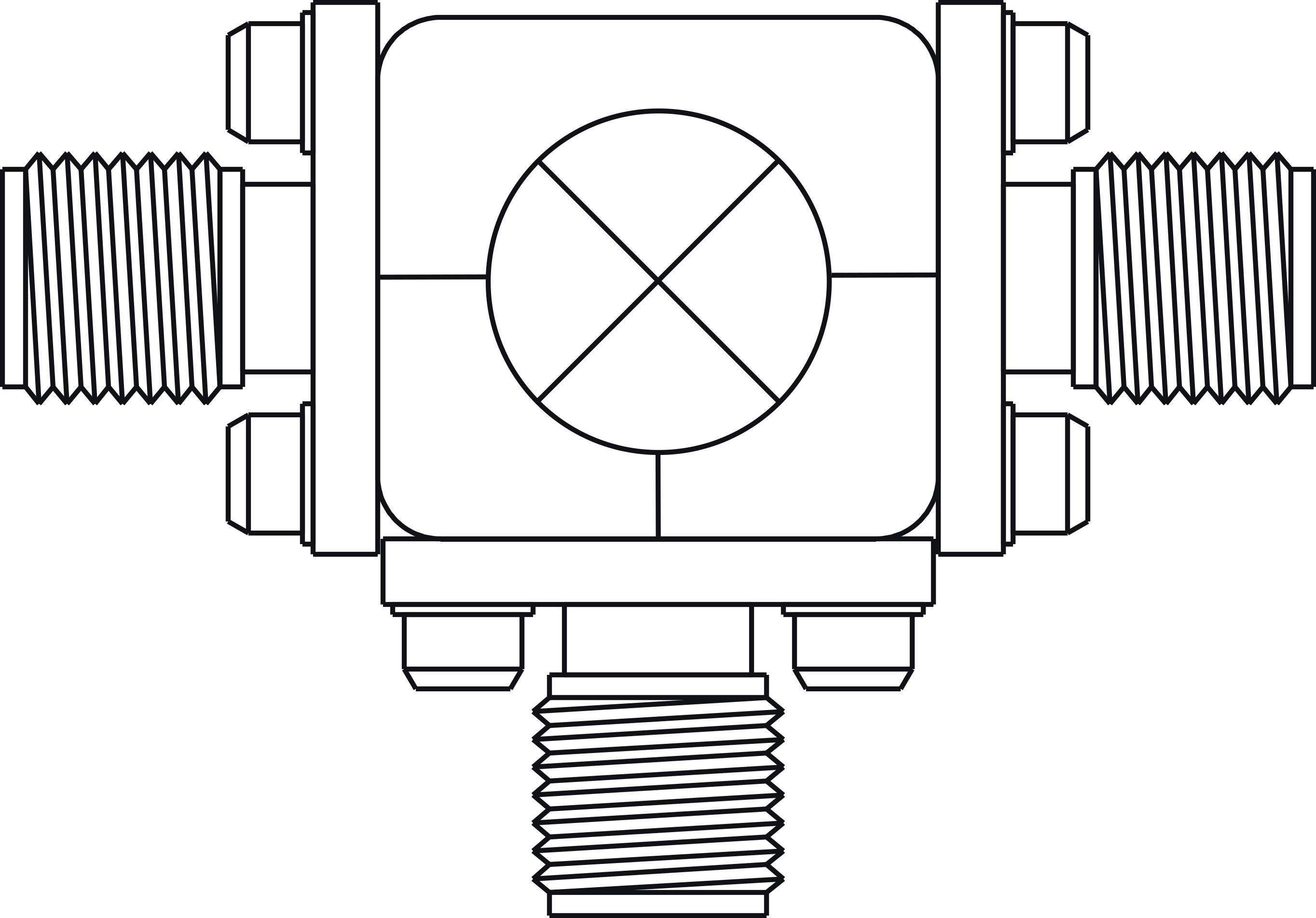
Port Diagram

Sales: 408-778-9952 | General: 408-778-4200 | Fax: 408-778-4300
Sales & Customer Support: [email protected]
Tech Support: [email protected]
The MM1-0626H is a passive double balanced MMIC mixer. It features excellent conversion loss, superior isolations and spurious performance across a broad bandwidth, in a highly miniaturized form factor. Accurate, nonlinear simulation models are available for Microwave Office® through the Marki Microwave PDK. The MM1-0626H is available as a wire bondable chip or an SMA connectorized package. The MM1-0626H is a superior alternative to Marki Microwave carrier and packaged M1 and M3 mixers.


| Part Number | Description | Package | Connectors | Green Status | Product Lifecycle | Export Classification |
|---|---|---|---|---|---|---|
| MM1-0626HS | GaAs MMIC Double Balanced Mixer | S | Standard | REACH RoHS | Released | EAR99 |
| Part Number | Description | Package | Connectors | Green Status | Product Lifecycle | Export Classification |
|---|---|---|---|---|---|---|
| MM1-0626HS | GaAs MMIC Double Balanced Mixer | S | Standard | REACH RoHS | Released | EAR99 |
MM1-0626HS
GaAs MMIC Double Balanced Mixer
| Revision Code | Revision Date | Comment |
|---|---|---|
| A | 2017-11-01 | Die shrunk from 1.48 x 1.18 mm2 to 1.37 x 1.17 mm2. CH package tolerance added. |
| B | 2021-12-01 | CH Package Outline Drawing Updated to include die number and logo |
MM1-0626HS
GaAs MMIC Double Balanced Mixer
| Port | Function | Connector Type | Description | DC Equivalent Circuit |
|---|---|---|---|---|
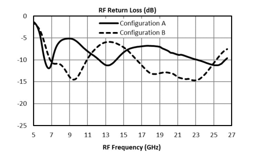
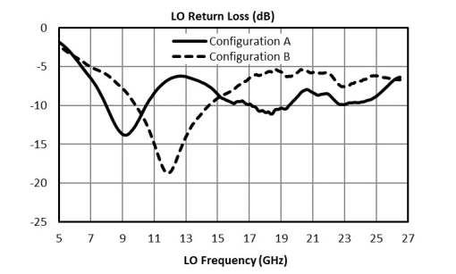
| Port 1 | LO | SMAF | Port 1 is DC open and AC matched to 50 Ohms from 6 to 26.5 GHz. Blocking capacitor is optional. |  |
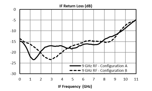
| Port 2 | IF | SMAF | Port 2 is DC coupled to the diodes. Blocking capacitor is optional. |  |
| Port 3 | RF | SMAF | Port 3 is DC open and AC matched to 50 Ohms from 6 to 26.5 GHz. Blocking capacitor is optional. | |
MM1-0626HS
GaAs MMIC Double Balanced Mixer
| Port | Function | Connector Type | Description | DC Equivalent Circuit |
|---|---|---|---|---|
| Port 1 | RF | SMAF | Port 1 is DC open and AC matched to 50 Ohms from 6 to 26.5 GHz. Blocking capacitor is optional. | |
| Port 2 | IF | SMAF | Port 2 is DC coupled to the diodes. Blocking capacitor is optional. | |
| Port 3 | LO | SMAF | Port 3 is DC open and AC matched to 50 Ohms from 6 to 26.5 GHz. Blocking capacitor is optional. | |
MM1-0626HS
GaAs MMIC Double Balanced Mixer
| Parameter | Maximum Rating | Unit |
|---|---|---|
| Maximum Operating Temperature | 100 | °C |
| Maximum Storage Temperature | 125 | °C |
| Minimum Operating Temperature | -55 | °C |
| Minimum Storage Temperature | -65 | °C |
| Port 2 DC Current | 15 | mA |
| RF Power Handling (RF+LO), 100°C | 20 | dBm |
| RF Power Handling (RF+LO), 25°C | 32 | dBm |
| Parameter | Details | Rating |
|---|---|---|
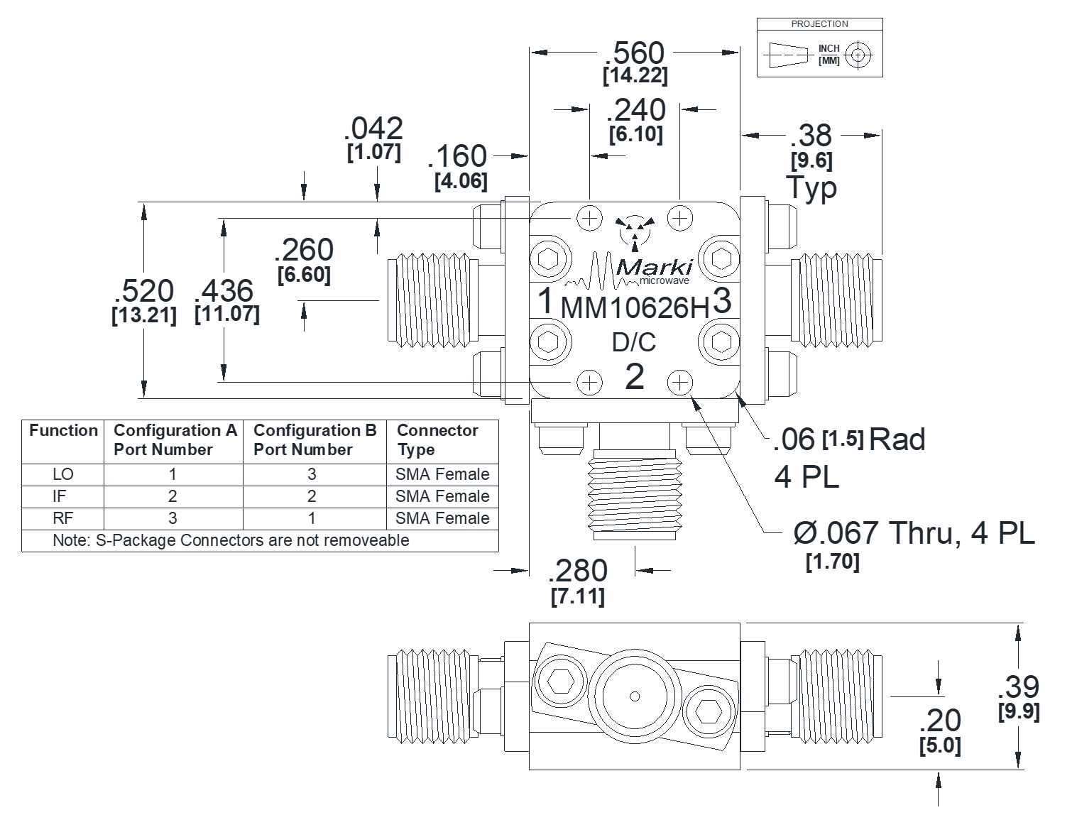
| Dimensions | - | 14.22 x 13.21mm |
| Parameter | Min | Nominal | Max | Unit |
|---|---|---|---|---|
| LO Input Power | 13 | - | 20 | - |
MM1-0626HS
GaAs MMIC Double Balanced Mixer
pecifications guaranteed from -55 to +100°C, measured in a 50Ω system. All bare die are 100% DC tested and 100% visually inspected. RF testing is performed on a sample basis to verify conformance to datasheet guaranteed specifications. Consult factory for more information.
| Parameter | Port Configuration | Test Conditions | Min | Typ | Max | Unit |
|---|---|---|---|---|---|---|
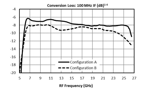
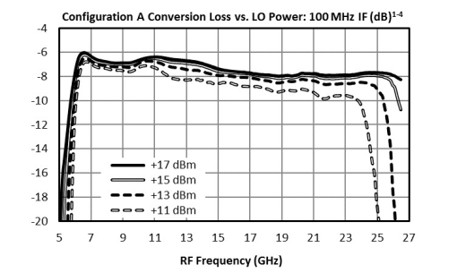
| Conversion Loss | A | LO/RF=6-26.5 IF=DC-9GHz LO drive level=15dBm | - | 7.5 | - | dB |
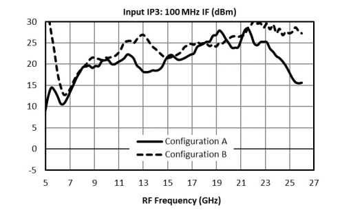
| Input IP3 | A | LO/RF=6-26.5GHz IF=DC-9GHz LO drive level=13-20dBm | - | 21 | - | dBm |
| Input P1dB | A | LO/RF=6-26.5GHz IF=DC-9GHz LO drive level=13-20dBm | - | 9 | - | dBm |
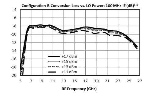
| Conversion Loss | B | LO/RF=6-26.5GHZ IF=DC-9GHz LO drive level=15dBm | - | 9 | - | dB |
| Input IP3 | B | LO/RF=6-26.5GHz IF=DC-9GHz LO drive level=13-20dBm | - | 23 | - | dBm |
| Input P1dB | B | LO/RF=6-26.5GHz IF=DC-9GHz LO drive level=13-20dBm | - | 9 | - | dBm |
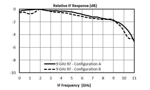
| IF Frequency Range | - | - | 0 | - | 9 | GHz |
| LO Frequency Range | - | - | 6 | - | 26.5 | GHz |
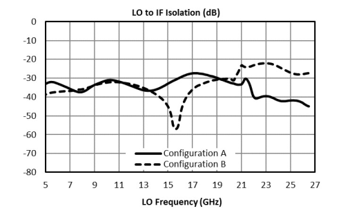
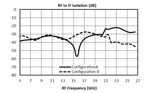
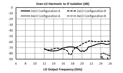
| LO-IF Isolation | - | LO/RF=6-26.5GHz IF=DC-9GHz LO drive level=13-20dBm | - | 34 | - | dB |
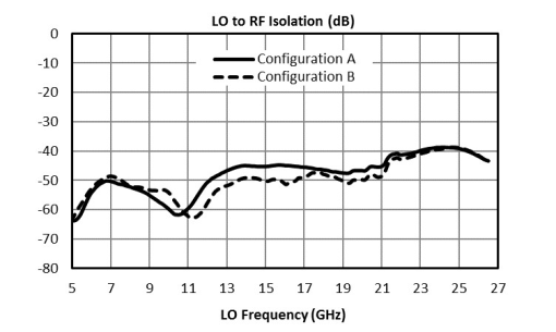
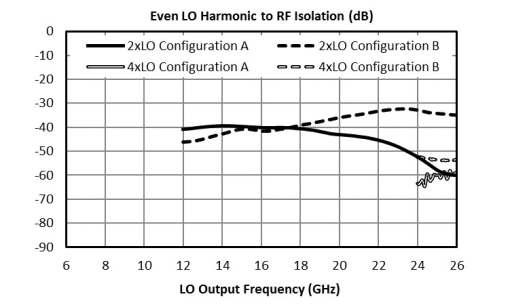
| LO-RF Isolation | - | LO/RF=6-26.5GHz IF=DC-9GHz LO drive level=13-20dBm | - | 47 | - | dB |
| RF Frequency Range | - | - | 6 | - | 26 | GHz |
| RF Frequency Range | - | - | 6 | - | 26.5 | GHz |
| RF-IF Isolation | - | LO/RF=6-26.5GHz IF=DC-9GHz LO drive level=13-20dBm | - | 35 | - | dB |
| Parameter | Port Configuration | Test Conditions | Min | Typ | Max | Unit |
|---|---|---|---|---|---|---|
| Conversion Loss | A | LO/RF=6-26.5 IF=DC-9GHz LO drive level=15dBm | - | 7.5 | - | dB |
| Input IP3 | A | LO/RF=6-26.5GHz IF=DC-9GHz LO drive level=13-20dBm | - | 21 | - | dBm |
| Input P1dB | A | LO/RF=6-26.5GHz IF=DC-9GHz LO drive level=13-20dBm | - | 9 | - | dBm |
| Conversion Loss | B | LO/RF=6-26.5GHZ IF=DC-9GHz LO drive level=15dBm | - | 9 | - | dB |
| Input IP3 | B | LO/RF=6-26.5GHz IF=DC-9GHz LO drive level=13-20dBm | - | 23 | - | dBm |
| Input P1dB | B | LO/RF=6-26.5GHz IF=DC-9GHz LO drive level=13-20dBm | - | 9 | - | dBm |
| IF Frequency Range | - | - | 0 | - | 9 | GHz |
| LO Frequency Range | - | - | 6 | - | 26.5 | GHz |
| LO-IF Isolation | - | LO/RF=6-26.5GHz IF=DC-9GHz LO drive level=13-20dBm | - | 34 | - | dB |
| LO-RF Isolation | - | LO/RF=6-26.5GHz IF=DC-9GHz LO drive level=13-20dBm | - | 47 | - | dB |
| RF Frequency Range | - | - | 6 | - | 26 | GHz |
| RF Frequency Range | - | - | 6 | - | 26.5 | GHz |
| RF-IF Isolation | - | LO/RF=6-26.5GHz IF=DC-9GHz LO drive level=13-20dBm | - | 35 | - | dB |
MM1-0626HS
GaAs MMIC Double Balanced Mixer
MM1-0626HS
GaAs MMIC Double Balanced Mixer
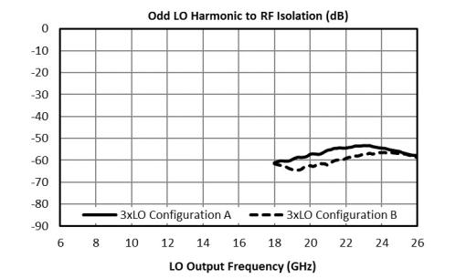
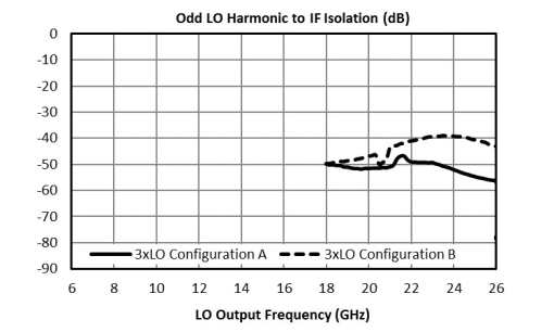
MM1-0626HS
GaAs MMIC Double Balanced Mixer
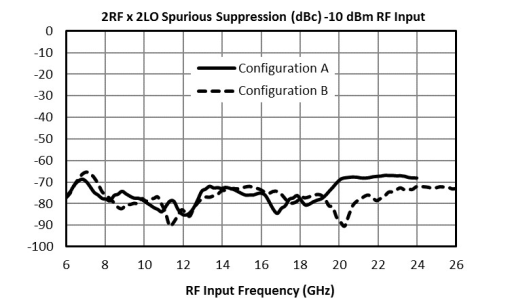
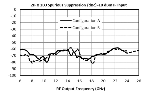
MM1-0626HS
GaAs MMIC Double Balanced Mixer