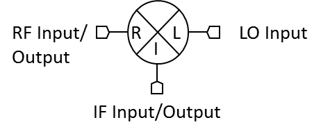
Port Diagram
NOT RECOMMENDED FOR NEW DESIGN
Sales: 408-778-9952 | General: 408-778-4200 | Fax: 408-778-4300
Sales & Customer Support: [email protected]
Tech Support: [email protected]
M2 triple balanced mixers are hybrid assemblies that have been hand-tuned to feature low conversion loss and high isolations. M2 mixers offer ultrabroadband overlapping frequency coverage on all 3 ports. Many M2 mixers have replaced with MM2 mixers with superior performance, repeatability, and availability. M2 mixers suitable for systems where an MM2 mixer is not available.
N/A
| Part Number | Description | Package | Connectors | Green Status | Product Lifecycle | Export Classification | Recommended Replacement |
|---|---|---|---|---|---|---|---|
| M2-0440LN | Triple-Balanced 4 - 40 GHz Mixer | N | Standard | Non-RoHS | Not Recommended for New Design | EAR99 | - |
| M2-0440LNV | Triple-Balanced 4 - 40 GHz Mixer | NV | Standard | Consult Factory | Not Recommended for New Design | EAR99 | - |
M2-0440LNV
Triple-Balanced 4 - 40 GHz Mixer
M2-0440LNV
Triple-Balanced 4 - 40 GHz Mixer
| Port | Function | Connector Type | Description | DC Equivalent Circuit |
|---|---|---|---|---|
| Port 1 | LO | 2.4F | Port 1 is DC short for the NV package. |  |
| Port 2 | IF | SMAF | Port 2 is diode connected for the NV Package. |  |
| Port 3 | RF | 2.4F | Port 3 is DC short for the NV Package. | |
M2-0440LNV
Triple-Balanced 4 - 40 GHz Mixer
| Parameter | Details | Rating |
|---|---|---|
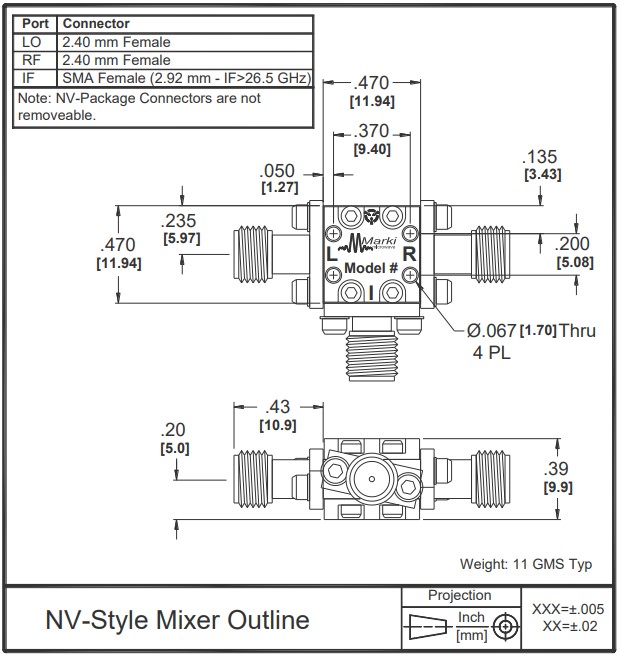
| Weight | Package name: NV | 11g |
| Dimensions | - | 11.94 x 11.94 mm |
| Parameter | Min | Nominal | Max | Unit |
|---|---|---|---|---|
| LO Input Power | 10 | - | 20 | - |
M2-0440LNV
Triple-Balanced 4 - 40 GHz Mixer
Specifications guaranteed from -55 to +100°C, measured in a 50-Ohm system.
| Parameter | Test Conditions | Min | Typ | Max | Unit |
|---|---|---|---|---|---|
| Conversion Loss | LO/RF=4-40 GHz IF=0.5-20 GHz | - | 10 | 15 | dB |
| Input IP3 1 | LO/RF=4-40 GHz L Diode drive level=10-20 dBm | - | 15 | - | dBm |
| Input P1dB | LO/RF=4-40 GHz L Diode drive level=10-20 dBm | - | 5 | - | dBm |
| LO-IF Isolation | LO/RF=4-40 GHz | - | 25 | - | dB |
| LO-RF Isolation | LO/RF=4-40 GHz | 18 | 25 | - | dB |
| RF-IF Isolation | LO/RF=4-40 GHz | - | 20 | - | dB |
| IF Frequency Range | - | 0.5 | - | 20 | GHz |
| RF Frequency Range | - | 4 | - | 40 | GHz |
[1] +13 dBm LO minimum recommended for best performance.
M2-0440LNV
Triple-Balanced 4 - 40 GHz Mixer


M2-0440LNV
Triple-Balanced 4 - 40 GHz Mixer
