Port Diagram

Sales: 408-778-9952 | General: 408-778-4200 | Fax: 408-778-4300
Sales & Customer Support: [email protected]
Tech Support: [email protected]
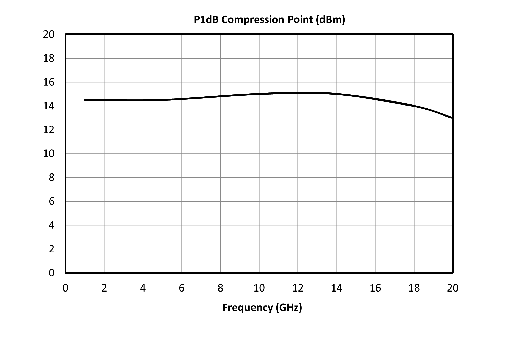
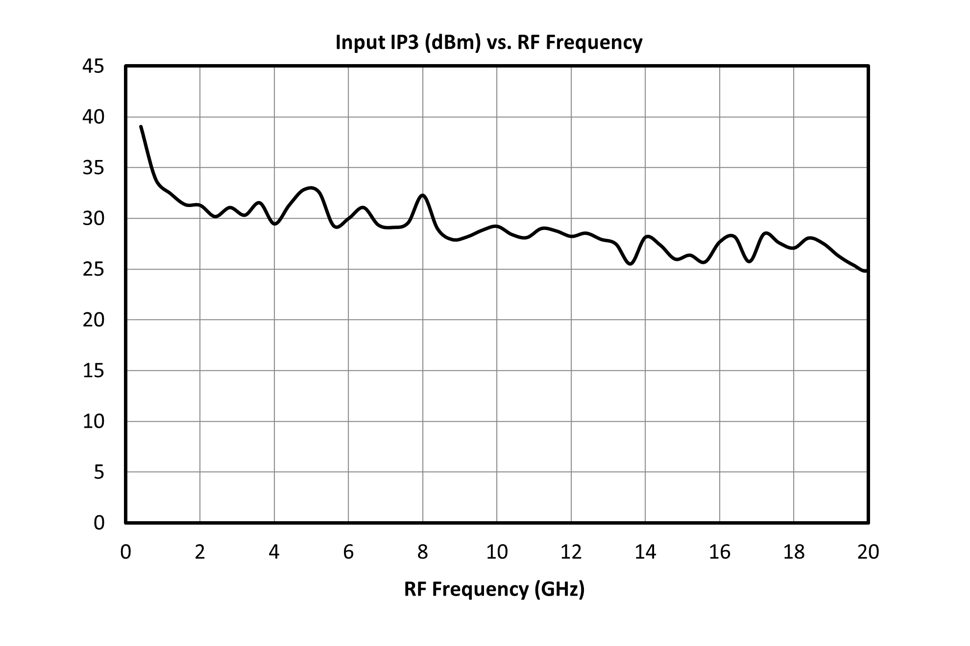
The HLM-20BH is a wide bandwidth GaAs Schottky diode signal limiter featuring high 30 dBm IP3 and high 4 W power handling over a broad DC-20 GHz bandwidth. It offers low 1 dB insertion loss and excellent return 15 dB loss from DC through K band and has a typical 1 dB compression point of 15 dBm. Its high power handling makes it ideal for protecting sensitive components and for applications requiring high linearity.

| Part Number | Description | Package | Connectors | Green Status | Product Lifecycle | Export Classification |
|---|---|---|---|---|---|---|
| HLM-20BH | High Power 20GHz Limiter | BH | - | REACH RoHS | Released | EAR99 |
| Part Number | Description | Package | Connectors | Green Status | Product Lifecycle | Export Classification |
|---|---|---|---|---|---|---|
| HLM-20BH | High Power 20GHz Limiter | BH | - | REACH RoHS | Released | EAR99 |
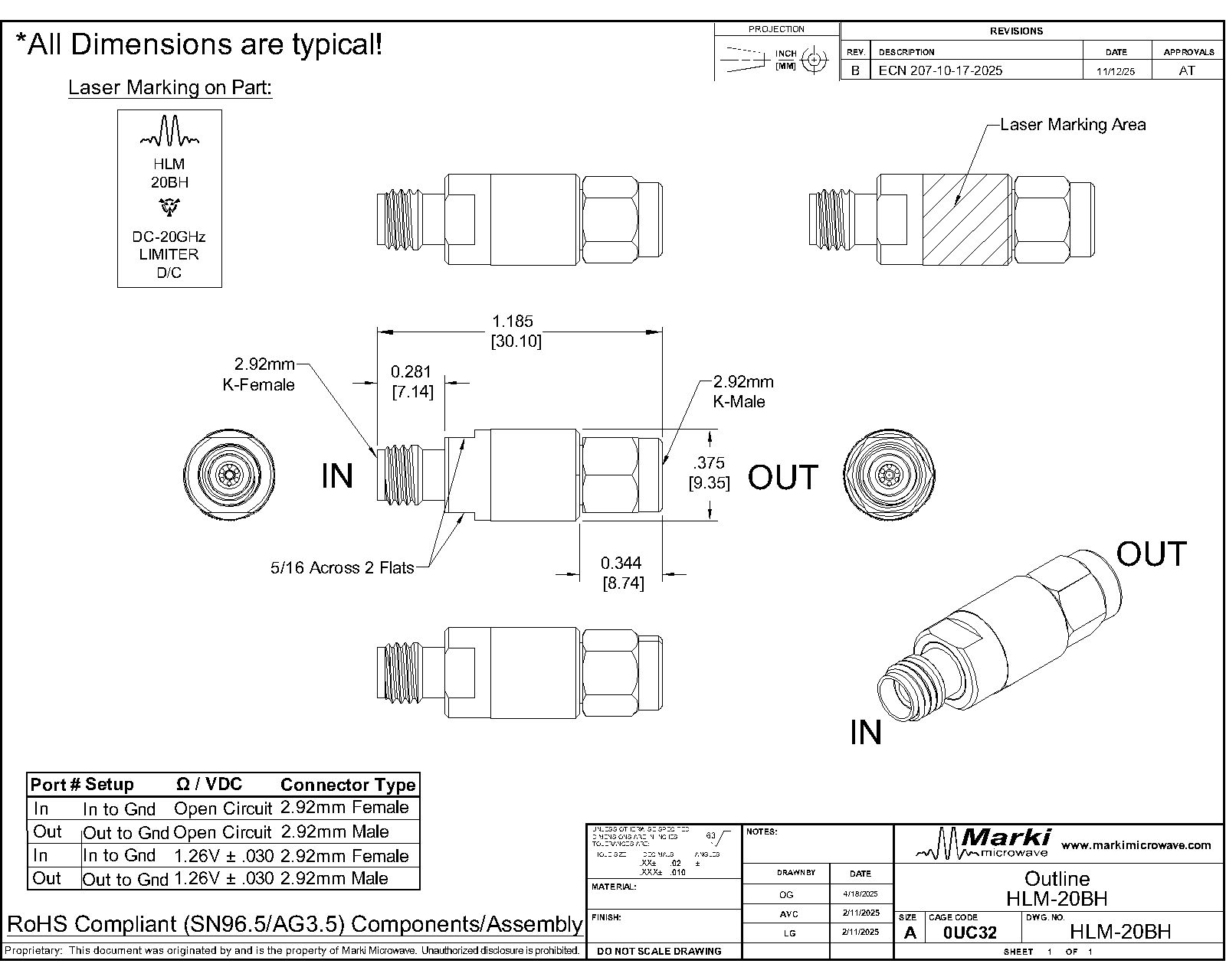
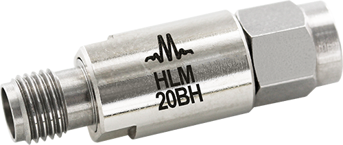
HLM-20BH
High Power 20GHz Limiter
| Revision Code | Revision Date | Comment |
|---|---|---|
| - | 2025-12-01 | Initial Release |
| A | 2026-06-02 | Added Recovery Time and Spike Leakage |
HLM-20BH
High Power 20GHz Limiter
| Port | Function | Connector Type | Description | DC Equivalent Circuit |
|---|---|---|---|---|
| GND | Ground | - | BH package ground is provided through metal housing and outer coax conductor. |  |
| IN | Input | 2.92F | The input port is diode connected for the BH package. |  |
| OUT | Output | 2.92M | The output port is diode connected for the BH package. | |
HLM-20BH
High Power 20GHz Limiter
| Parameter | Maximum Rating | Unit |
|---|---|---|
| Maximum Operating Temperature | 100 | °C |
| Maximum Storage Temperature | 125 | °C |
| Minimum Operating Temperature | -55 | °C |
| Minimum Storage Temperature | -65 | °C |
| RF Power Handling , Average 1 | 4 | W |
RF Power Handling represents an instantaneous, catastrophic limit and it isn’t derated for frequency, temperature, pulse conditions, or unit to unit variation
[1] CW @ 10 GHz, 25°C
| Parameter | Details | Rating |
|---|---|---|
| Weight | Package name: BH | 9.2g |
| Dimensions | - | 30.1 x 9.5 mm |
HLM-20BH
High Power 20GHz Limiter
The electrical specifications apply at TA=+25°C in a 50Ω system. Typical data shown is for the connectorized BH-package limiter unless otherwise specified.
| Parameter | Test Conditions | Minimum Frequency (GHz) | Maximum Frequency (GHz) | Min | Typ | Max | Unit |
|---|---|---|---|---|---|---|---|
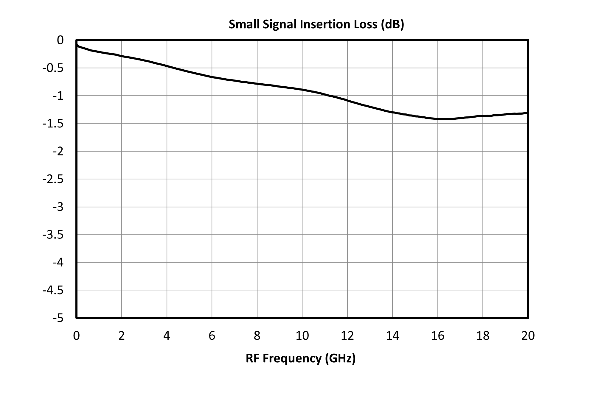
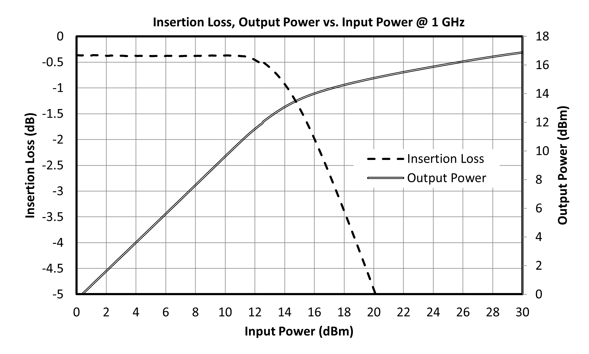
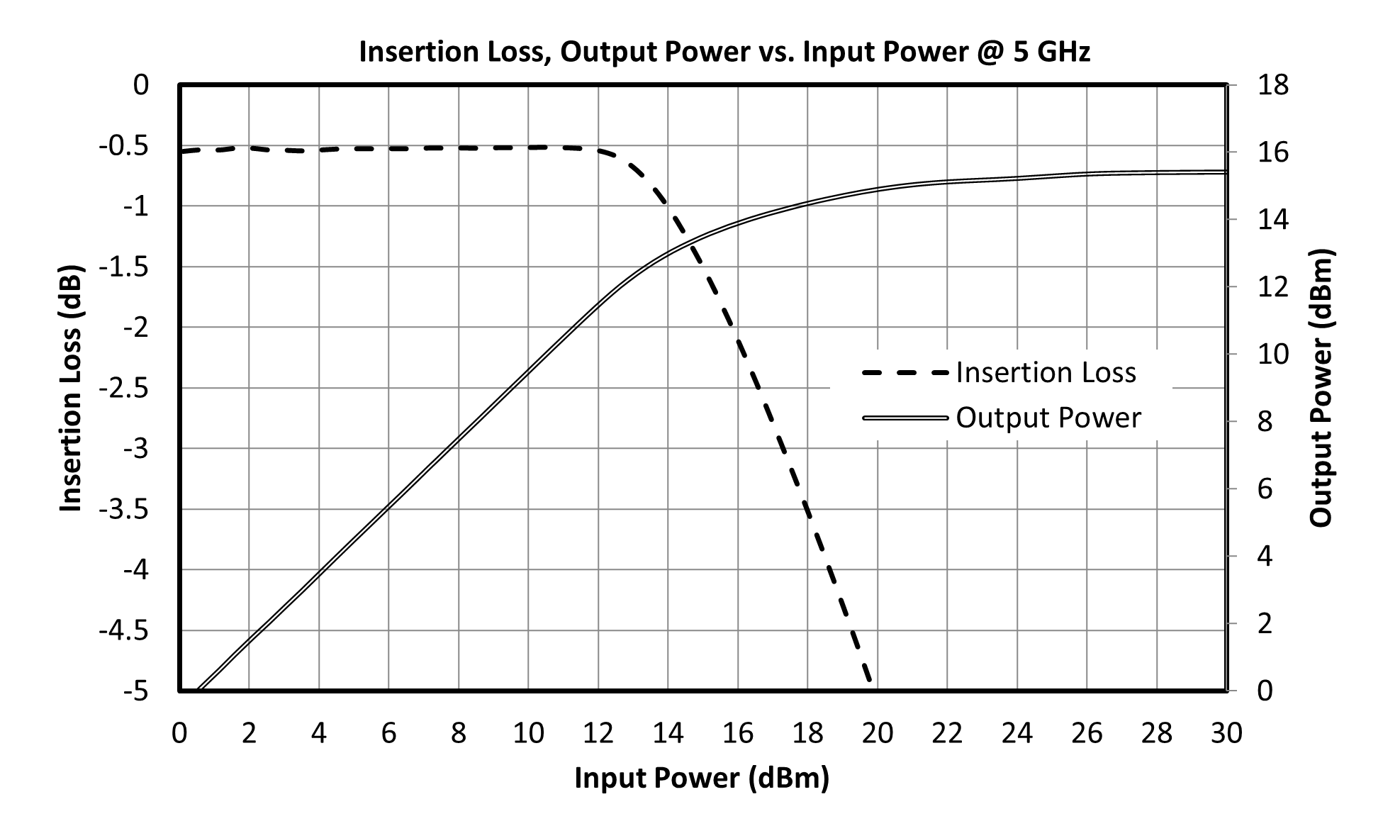
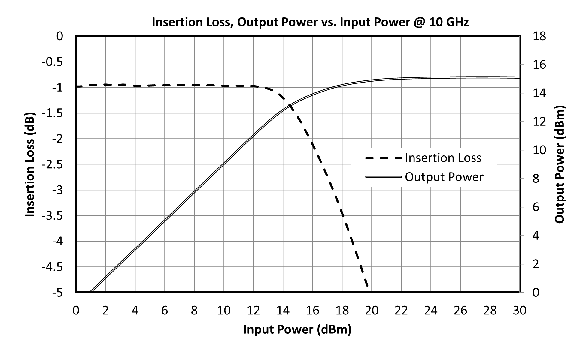
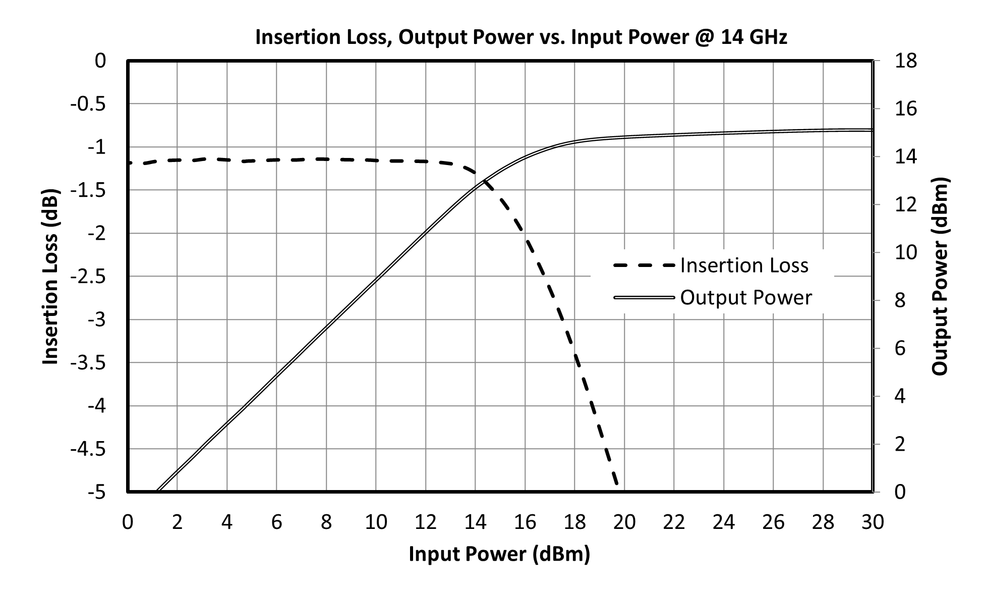
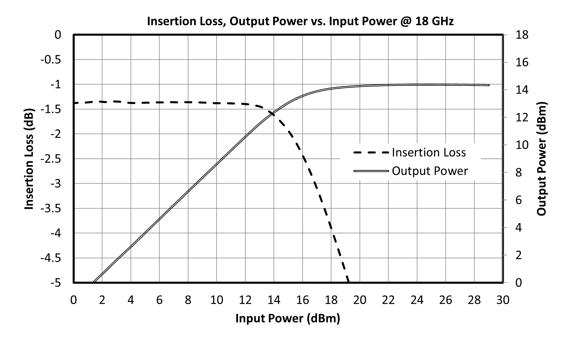
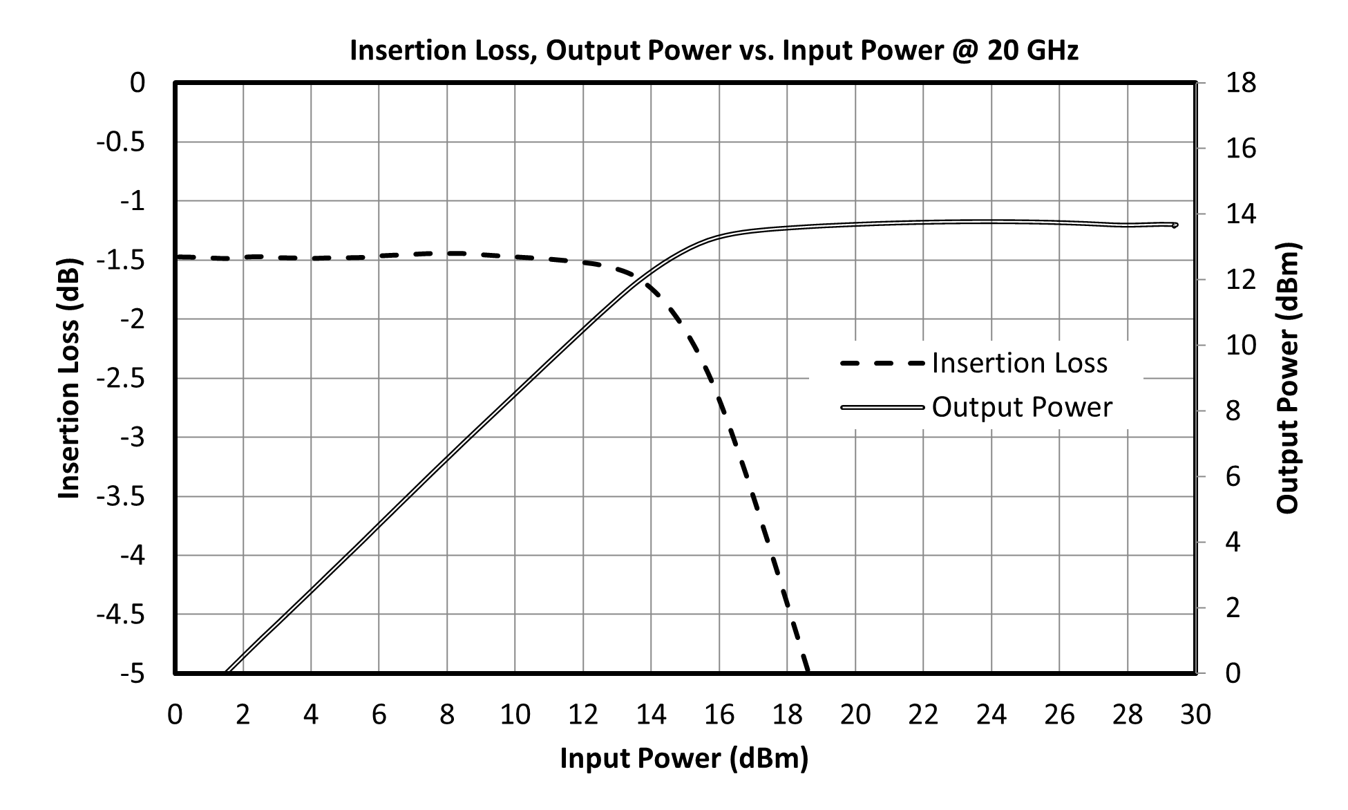
| Insertion Loss | - | 0 | 20 | - | 1 | - | dB |
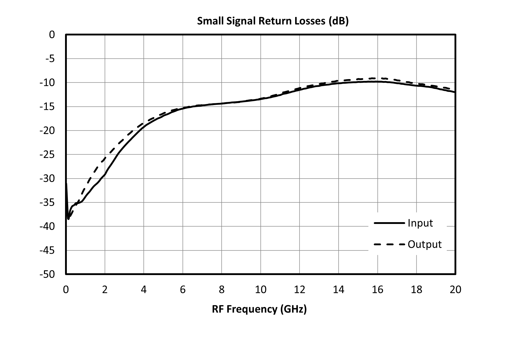
| Return Loss | - | 0 | 20 | - | 15 | - | dB |
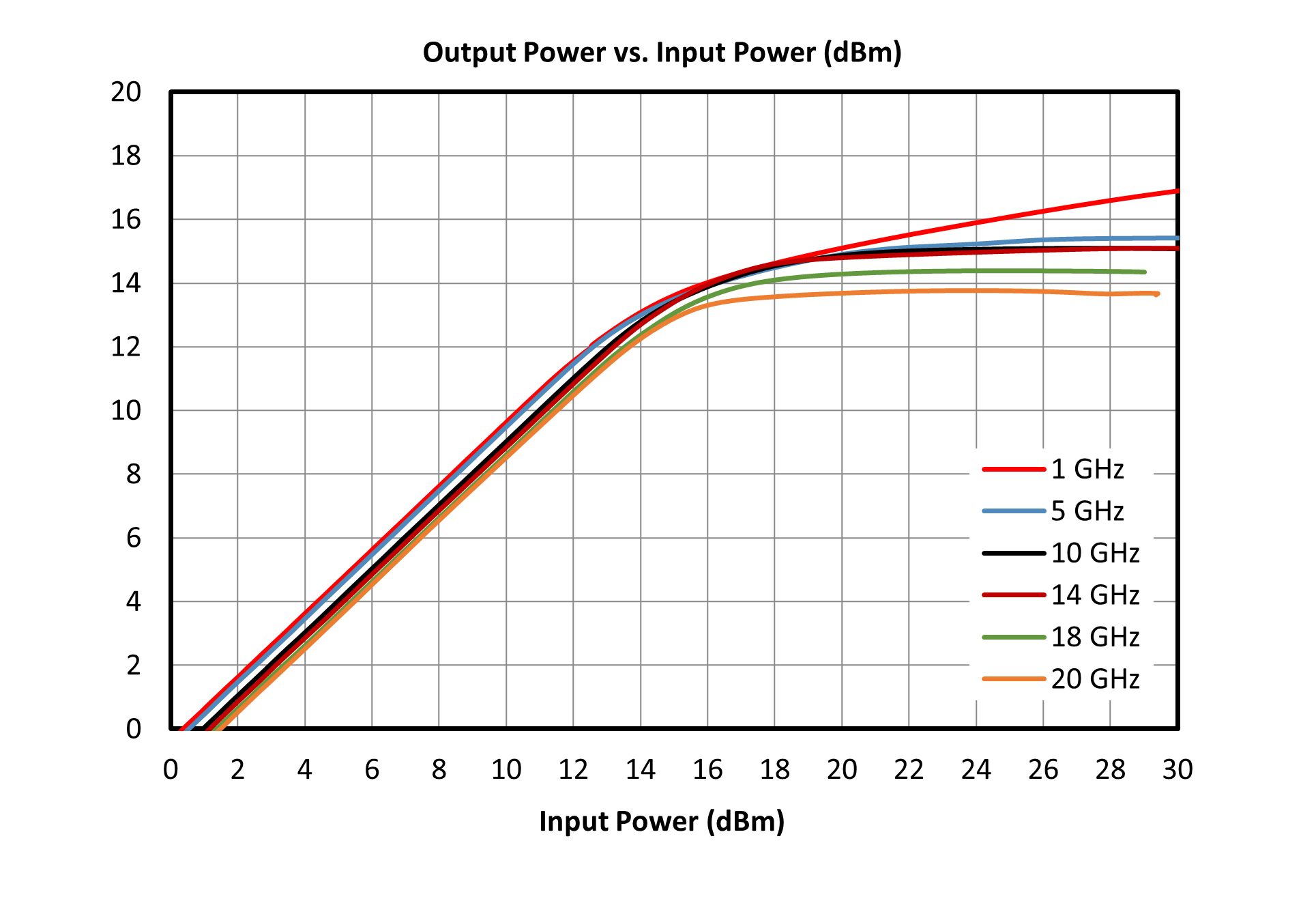
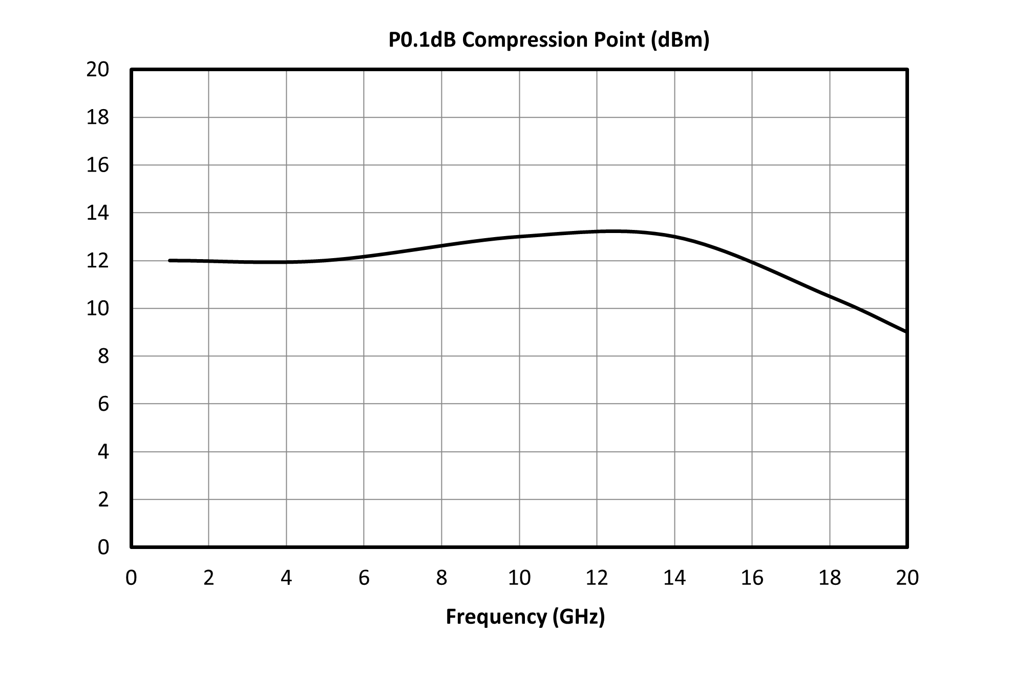
| Flat Leakage | 1 GHz CW | - | - | - | 17 | - | dBm |
| Flat Leakage | 5 GHz CW | - | - | - | 15.3 | - | dBm |
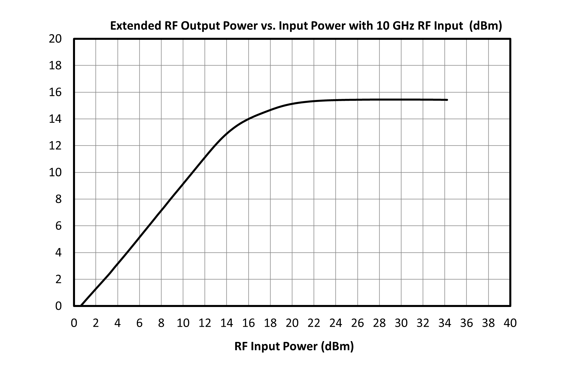
| Flat Leakage | 10 GHz CW | - | - | - | 15 | - | dBm |
| Flat Leakage | 14 GHz CW | - | - | - | 15 | - | dBm |
| Flat Leakage | 18 GHz CW | - | - | - | 14.3 | - | dBm |
| Flat Leakage | 20 GHz CW | - | - | - | 13.7 | - | dBm |
| Input IP3 | -5dBm Tone Powers at 1 MHz Spacing | 0 | 20 | - | 30 | - | dBm |
| Spike Leakage | - | - | - | - | 0.1 | - | erg |
| Recovery Time | - | - | - | - | 8 | - | ns |
| Parameter | Test Conditions | Minimum Frequency (GHz) | Maximum Frequency (GHz) | Min | Typ | Max | Unit |
|---|---|---|---|---|---|---|---|
| Insertion Loss | - | 0 | 20 | - | 1 | - | dB |
| Return Loss | - | 0 | 20 | - | 15 | - | dB |
| Flat Leakage | 1 GHz CW | - | - | - | 17 | - | dBm |
| Flat Leakage | 5 GHz CW | - | - | - | 15.3 | - | dBm |
| Flat Leakage | 10 GHz CW | - | - | - | 15 | - | dBm |
| Flat Leakage | 14 GHz CW | - | - | - | 15 | - | dBm |
| Flat Leakage | 18 GHz CW | - | - | - | 14.3 | - | dBm |
| Flat Leakage | 20 GHz CW | - | - | - | 13.7 | - | dBm |
| Input IP3 | -5dBm Tone Powers at 1 MHz Spacing | 0 | 20 | - | 30 | - | dBm |
| Spike Leakage | - | - | - | - | 0.1 | - | erg |
| Recovery Time | - | - | - | - | 8 | - | ns |
HLM-20BH
High Power 20GHz Limiter
HLM-20BH
High Power 20GHz Limiter
HLM-20BH
High Power 20GHz Limiter