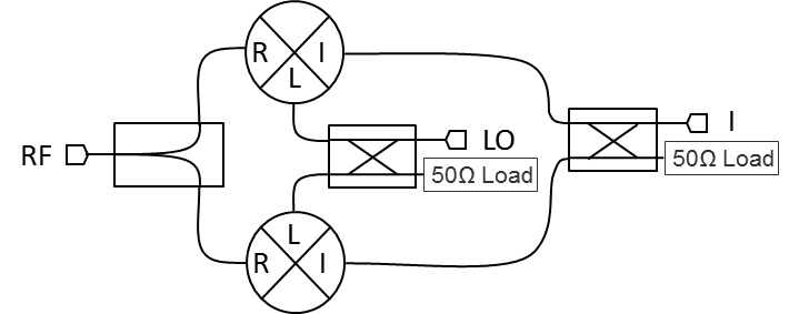
Port Diagram

NOT RECOMMENDED FOR NEW DESIGN
Sales: 408-778-9952 | General: 408-778-4200 | Fax: 408-778-4300
Sales & Customer Support: [email protected]
Tech Support: [email protected]
The IR-4509 is an image reject mixer that performs single sided downconversion, or "image reject" conversion, and offers excellent image rejection across broad bandwidths. This broadband mixer spans 4.5 to 9 GHz on the RF and LO ports with an IF from 50 to 90 MHz. IR series mixers have generally been replaced with MMIQ mixers with superior performance, repeatability, and availability. IR series mixers are still used in legacy systems and are suitable for laboratory use.

N/A
| Part Number | Description | Package | Connectors | Green Status | Product Lifecycle | Export Classification | Recommended Replacement |
|---|---|---|---|---|---|---|---|
| IR-4509MXP | Image Reject Double-Balanced 4.5 - 9.0 GHz Mixers | XP | Standard | Non-RoHS | End of Life | EAR99 | MMIQ-0416LSQH-0R518 |
| IR-4509MXP-1 | Image Reject Double-Balanced 4.5 - 9.0 GHz Mixers | XP | Standard | Non-RoHS | End of Life | EAR99 | MMIQ-0416LSQH-0R518 |
| IR-4509MXP-2 | Image Reject Double-Balanced 4.5 - 9.0 GHz Mixers | XP | Standard | Non-RoHS | Not Recommended for New Design | EAR99 | - |
| IR-4509LXP | Image Reject Double-Balanced 4.5 - 9.0 GHz Mixers | XP | Standard | Non-RoHS | Not Recommended for New Design | EAR99 | - |
IR-4509LXP
Image Reject Double-Balanced 4.5 - 9.0 GHz Mixers
IR-4509LXP
Image Reject Double-Balanced 4.5 - 9.0 GHz Mixers
| Port | Function | Connector Type | Description | DC Equivalent Circuit |
|---|---|---|---|---|
| GND | Ground | - | XP package ground taken through metal housing. |  |
| I | I Input / Output | SMAF | I port is diode coupled and AC matched to 50Ω over the specified I port frequency range. |  |
| LO | LO Input | SMAF | LO port is DC short and AC matched to 50Ω over the specified LO frequency range. |  |
| Q | Q Input / Output | SMAF | Q port is diode coupled and AC matched to 50Ω over the specified Q port frequency range. | |
| RF | RF Input / Output | SMAF | RF port is DC short and AC matched to 50Ω over the specified RF frequency range. | |
IR-4509LXP
Image Reject Double-Balanced 4.5 - 9.0 GHz Mixers
| Parameter | Details | Rating |
|---|---|---|
| Weight | Package name: XP | 30g |
| Dimensions | - | 20.32 x 20.32 mm |
| Parameter | Min | Nominal | Max | Unit |
|---|---|---|---|---|
| LO Input Power | 10 | - | 13 | - |
IR-4509LXP
Image Reject Double-Balanced 4.5 - 9.0 GHz Mixers
Specifications guaranteed from -55 to +100°C, measured in a 50-Ohm system.
| Parameter | Test Conditions | Minimum Frequency (GHz) | Maximum Frequency (GHz) | Min | Typ | Max | Unit |
|---|---|---|---|---|---|---|---|
| Conversion Loss | LO/RF=4.5-9 GHz IF=0.05-0.09 GHz | 4.5 | 9 | - | 5.5 | 8 | dB |
| Image Rejection | LO/RF=4.5-9 GHz IF=0.05-0.09 GHz | 4.5 | 9 | 15 | 23 | - | dB |
| Input IP3 | LO/RF=4.5-9 GHz IF=0.05-0.09 GHz L diode level 10-13 dBm | 4.5 | 9 | - | 14 | - | dBm |
| Input P1dB | LO/RF=4.5-9 GHz IF=0.05-0.09 GHz L diode level 10-13 dBm | 4.5 | 9 | - | 4 | - | dBm |
| LO-IF Isolation | LO/RF=4.5-9 GHz IF=0.05-0.09 GHz | 4.5 | 9 | - | 25 | - | dB |
| LO-RF Isolation | LO/RF=4.5-9 GHz IF=0.05-0.09 GHz | 4.5 | 9 | 20 | 30 | - | dB |
| RF-IF Isolation | LO/RF=4.5-9 GHz IF=0.05-0.09 GHz | 4.5 | 9 | - | 25 | - | dB |
| IF Frequency Range | - | - | - | 0.05 | - | 0.09 | GHz |
| RF Frequency Range | - | - | - | 4.5 | - | 9 | GHz |
IR-4509LXP
Image Reject Double-Balanced 4.5 - 9.0 GHz Mixers


