Absolute Maximum Ratings
| Parameter | Maximum Rating | Unit |
|---|---|---|
| RF Power Handling | 50 | W |
Sales: 408-778-9952 | General: 408-778-4200 | Fax: 408-778-4300
Sales & Customer Support: [email protected]
Tech Support: [email protected]
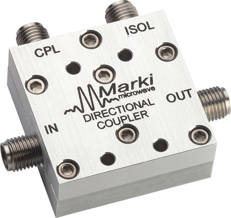
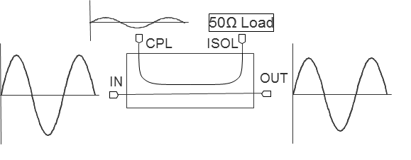
The CA-26 is a low loss directional coupler capable of operation to 26.5 GHz. This coupler features a unique air-line construction that simultaneously enables extremely low loss, minimal return loss, and outstanding directivity throughout the entire frequency range to 26.5 GHz. This coupler can be used for low loss and high power applications. The useable operating frequencies extend below 1 GHz for applications where calibration of the frequency response is available.
N/A
| Part Number | Description | Connectors | Green Status | Product Lifecycle | Export Classification |
|---|---|---|---|---|---|
| CA-26 | Air-Line Directional Coupler | Standard | REACH RoHS | Released | EAR99 |
| Part Number | Description | Connectors | Green Status | Product Lifecycle | Export Classification |
|---|---|---|---|---|---|
| CA-26 | Air-Line Directional Coupler | Standard | REACH RoHS | Released | EAR99 |
CA-26
Air-Line Directional Coupler
| Revision Code | Revision Date | Comment |
|---|---|---|
| - | 2011-11-01 | Datasheet Initial Release |
CA-26
Air-Line Directional Coupler
| Parameter | Maximum Rating | Unit |
|---|---|---|
| RF Power Handling | 50 | W |
| Parameter | Details | Rating |
|---|---|---|
| Weight | - | 36g |
| Dimensions | - | 30.48 x 30.48 mm |
CA-26
Air-Line Directional Coupler
Specifications guaranteed when operated in a 50Ω system.
| Parameter | Test Conditions | Minimum Frequency (GHz) | Maximum Frequency (GHz) | Min | Typ | Max | Unit |
|---|---|---|---|---|---|---|---|
| Directivity | - | 1 | 18 | - | 24 | - | dB |
| Directivity | - | 18 | 26.5 | 13 | 18 | - | dB |
| Direct Line Insertion Loss | DC-18 | - | - | - | 0.25 | 0.5 | dB |
| Direct Line Insertion Loss | - | 18 | 26.5 | - | 0.35 | 0.7 | dB |
| Mean Coupling | - | 26 | - | - | 27 | - | dB |
| Mean Coupling | - | 1 | - | - | 53 | - | dB |
| VSWR | - | 1 | 18 | - | 1.1 | 1.35 | - |
| VSWR | - | 18 | 26.5 | - | 1.3 | 1.6 | - |
CA-26
Air-Line Directional Coupler


CA-26
Air-Line Directional Coupler
